
For solar EPC companies in India and across the globe, comprehensive engineering documentation is the backbone of successful project execution. Whether you’re developing a 1 MW rooftop installation or a 100 MW ground mount solar farm, having the right solar drawings can mean the difference between smooth approvals and costly delays. In 2026, regulatory requirements are more stringent than ever, and clients expect detailed, accurate documentation that demonstrates technical expertise and ensures project viability.
This comprehensive guide breaks down the 17 essential solar drawings and engineering documents that every EPC company must include in their project documentation. From single-line diagrams to structural calculations, we’ll explain what each drawing contains, why it’s critical for your project, and the common mistakes that can derail your timeline and budget.
Understanding Solar Drawings: The Foundation of Successful Solar Projects
Solar drawings are technical documents that provide detailed visual and written specifications for every aspect of a solar power installation. These engineering documents serve multiple critical purposes: they guide construction teams during installation, satisfy regulatory requirements for permits and approvals, enable accurate procurement of materials, and provide a permanent record for operations and maintenance.
In India’s rapidly growing solar market, where the country aims to achieve 500 GW of renewable energy capacity, the quality of your solar drawings directly impacts project success. Incomplete or inaccurate documentation leads to permit rejections, construction delays, cost overruns, and potential safety issues. Professional engineering design ensures that your project meets all technical standards, complies with Central Electricity Authority (CEA) regulations, and maximizes return on investment for your clients.

The 17 essential documents we’ll cover fall into several categories: electrical design drawings, civil and structural engineering documents, safety and compliance drawings, and project management documentation. Each plays a specific role in the project lifecycle, from initial feasibility through construction and commissioning. Let’s explore each one in detail.
1. Single Line Diagram (SLD): The Electrical Blueprint
The Single Line Diagram is arguably the most important electrical drawing for any solar project. This simplified schematic shows the entire electrical system from solar panels to the grid connection point using standardized symbols and single lines to represent three-phase power systems. The SLD provides a clear overview of how electrical energy flows through your installation.
A comprehensive SLD for MW-scale projects includes solar array configuration, DC combiner boxes, inverters, AC distribution panels, transformers (if applicable), protection devices (circuit breakers, fuses, surge protection), metering equipment, and the grid interconnection point. It also specifies voltage levels at each stage, current ratings, and cable specifications.
This drawing is required for electrical permit approvals from state electricity boards and the Chief Electrical Inspector’s office. Utility companies review the SLD to approve grid interconnection applications. Without an accurate, detailed SLD, your project cannot proceed to installation.
Common mistakes to avoid: Missing or incorrectly rated protection devices, failure to show all isolation points, incorrect voltage drop calculations, and omitting earthing connections. These errors result in permit rejections and require costly redesign work.
2. Site Layout Drawing: Optimizing Land Utilization
The Site Layout Drawing provides a bird’s-eye view of your entire solar installation, showing how all components are arranged on the available land or rooftop. This drawing is essential for understanding spatial relationships and ensuring efficient use of available area.
Key components include solar panel array arrangement with row spacing, inverter and transformer locations, cable trench routes, access roads and pathways, boundary fencing, control room or monitoring station, drainage systems, and setback distances from property boundaries. For ground mount projects in India, the layout must account for land topography, existing vegetation, and seasonal water flow patterns.
This drawing is critical for land feasibility assessment and construction planning. It helps contractors understand site logistics, material staging areas, and construction sequencing. Municipal authorities review site layouts to ensure compliance with setback requirements and land use regulations.
Common errors: Inadequate spacing between rows leading to shading losses, poor access planning that complicates maintenance, failure to account for drainage requirements, and not considering future expansion possibilities. Professional solar feasibility studies help identify these issues before detailed design begins.
3. Module Layout Drawing: Maximizing Energy Generation
While the site layout shows overall arrangement, the Module Layout Drawing provides panel-level detail. This drawing shows the exact position of every solar module, string configurations, and electrical connections between panels.
The module layout includes panel orientation (landscape or portrait), string grouping with series and parallel connections, module specifications (wattage, voltage, current), and integration with shadow analysis results. For rooftop projects, it shows how panels work around obstacles like HVAC units, skylights, and roof penetrations.
This level of detail is essential for maximizing energy generation and ensuring proper electrical design. String configurations must match inverter input specifications, and panel grouping affects system performance and monitoring capabilities. The module layout also guides installation crews during panel mounting.
Mistakes to avoid: Improper string sizing that doesn’t match inverter MPPT voltage windows, mixing panels with different specifications in the same string, ignoring micro-shading from nearby obstacles, and creating strings that are difficult to access for maintenance.
4. Electrical Schematic Diagram: Detailed Circuit Design
The Electrical Schematic Diagram goes beyond the simplified SLD to show component-level electrical connections. While the SLD provides an overview, the schematic gives contractors the detailed information needed for actual wiring and installation.
This drawing includes detailed wiring between all components, junction box internal connections, combiner box schematics, inverter input and output wiring, AC distribution panel layouts, and cable specifications with color coding. It shows every wire, terminal, and connection point in the system.
Electrical contractors rely on these schematics for installation and troubleshooting. During commissioning, technicians use schematics to verify correct connections and diagnose any issues. For operations and maintenance, these drawings are invaluable for understanding system configuration.
Common pitfalls: Incorrect cable sizing leading to voltage drop issues, missing polarity markings on DC connections, inadequate specification of connector types, and failure to show grounding connections at every junction point.
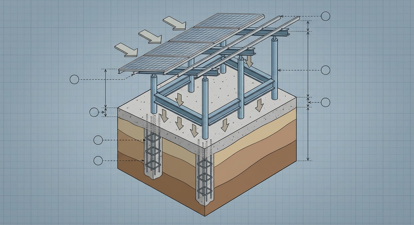
5. Civil & Structural Drawings: Engineering the Foundation
The Civil and Structural Drawings are critical for ensuring your solar installation can withstand environmental loads and remain stable throughout its 25-year lifespan. These drawings cover foundation design, mounting structure specifications, and structural connections.
Key components include foundation drawings with dimensions and reinforcement details, mounting structure assembly drawings, anchor bolt specifications and placement, load transfer mechanisms, and soil bearing capacity requirements. For rooftop installations, structural drawings show roof attachment methods and load distribution across the building structure.
In India, structural engineering must account for regional variations in wind speeds, seismic zones, and soil conditions. Projects in coastal areas face higher wind loads, while installations in seismic zones require additional structural considerations. Professional solar civil and structural engineering services ensure compliance with IS codes (Indian Standards) including IS 875 for wind loads and IS 1893 for seismic design.
Common mistakes: Using generic foundation designs without site-specific soil testing, inadequate wind load calculations, failure to account for corrosion in coastal environments, and not considering seasonal ground movement in expansive soils. These errors can lead to structural failures and safety hazards.
6. Earthing & Lightning Protection Drawing: Safety First
The Earthing and Lightning Protection Drawing shows the grounding system that protects both equipment and personnel from electrical faults and lightning strikes. This is a critical safety document that must comply with CEA regulations and IS 3043 standards.
The drawing includes earthing grid layout with conductor specifications, earth pit locations and specifications, lightning arrestor placement, bonding connections for all metallic structures, and earth resistance testing points. For large installations, the earthing system forms a comprehensive grid that connects all equipment to a common ground reference.
Proper earthing is required for electrical safety certification and insurance approval. It protects expensive inverters and other equipment from lightning damage and ensures safe operation during fault conditions. In India’s monsoon climate, robust lightning protection is especially important.
Common mistakes that compromise safety: Inadequate earth electrode sizing, poor soil conductivity without enhancement measures, missing bonding connections on mounting structures, and insufficient lightning protection coverage for large arrays.
7. Cable Routing & Trenching Drawing: The Hidden Infrastructure
The Cable Routing and Trenching Drawing shows the underground and above-ground pathways for all electrical cables. This often-overlooked drawing is essential for proper installation and future maintenance access.
Details include DC cable routes from arrays to inverters, AC cable routes from inverters to transformers and grid connection, trench depth and width specifications, cable protection methods (conduits, cable trays), separation distances between power and communication cables, and marker post locations for buried cables. The drawing also specifies cable entry points into buildings and equipment enclosures.
Proper cable routing planning prevents costly rework during construction. Contractors need this information to excavate trenches before panel installation begins. Poor planning leads to cable damage, voltage drop issues, and difficulty accessing cables for future repairs or system expansion.
Best practices for large-scale installations: Maintain adequate separation between DC and AC cables, provide extra conduit capacity for future expansion, use appropriate cable protection in high-traffic areas, and create detailed as-built records of buried cable locations.
8. Inverter & Transformer Layout: Power Conversion Centers
The Inverter and Transformer Layout Drawing shows the placement and specifications of power conversion equipment. These are the most expensive components in a solar system, so proper placement is critical for performance and longevity.
The layout includes inverter locations with model specifications, transformer placement (for medium-voltage systems), clearance requirements for ventilation and maintenance, cable entry and exit points, and integration with monitoring and control systems. For outdoor installations, the drawing shows weather protection enclosures and shading structures.
Strategic placement affects system efficiency and maintenance costs. Inverters should be located to minimize DC cable runs (reducing losses), positioned for adequate ventilation (preventing thermal derating), and placed for easy access during maintenance. Transformer locations must consider both electrical efficiency and noise impact on nearby areas.
Common layout mistakes: Placing inverters in direct sunlight without shading, inadequate clearance for door opening and equipment removal, poor ventilation leading to overheating, and locating equipment in areas prone to flooding during monsoons.
9. Protection & Metering Diagram: Monitoring and Safety
The Protection and Metering Diagram details all protective devices and measurement equipment in the system. This drawing ensures comprehensive protection against electrical faults and enables accurate performance monitoring.
Components include DC circuit breakers and fuses, AC distribution boards (ACDBs) with protection devices, residual current devices (RCDs) for safety, surge protection devices (SPDs) at multiple levels, generation meters and export meters, and monitoring system integration. The diagram shows protection coordination to ensure that faults are isolated at the appropriate level without affecting the entire system.
This documentation is required for utility interconnection approval and compliance with CEA (Technical Standards for Connectivity) regulations. Utilities need to verify that your system has adequate protection to prevent grid disturbances. Insurance companies also review protection schemes when underwriting solar projects.
Compliance considerations: Protection devices must be rated for DC applications (which differ from AC), coordination studies ensure selectivity, and metering must meet utility accuracy requirements for net metering or power purchase agreements.
10. Bill of Materials (BOM): Procurement Precision
The Bill of Materials is a comprehensive list of every component required for the project, with specifications, quantities, and often supplier information. While not a drawing in the traditional sense, the BOM is an essential engineering document that flows directly from the design drawings.
A detailed BOM includes solar modules with exact model numbers and quantities, inverters and transformers, mounting structure components (rails, clamps, fasteners), electrical components (cables, connectors, junction boxes, protection devices), civil materials (concrete, rebar, anchors), and balance of system items (monitoring equipment, earthing materials, conduits).
An accurate BOM prevents cost overruns and procurement delays. It enables competitive bidding with suppliers, ensures compatibility between components, and provides a baseline for project cost estimation. The BOM must be perfectly synchronized with engineering drawings to avoid shortages or excess materials on site.
Common errors in quantity calculations: Underestimating cable lengths by not accounting for routing paths, missing small components like cable ties and labels, not including spare parts for commissioning, and failing to account for wastage factors in civil materials.
11. 3D Model & Visualization: Bringing Designs to Life
Modern 3D modeling and visualization has become an essential tool for solar project design and communication. While 2D drawings provide technical specifications, 3D models help stakeholders visualize the completed project and identify potential issues before construction begins.
A comprehensive 3D model includes accurate terrain modeling, photorealistic rendering of installed panels and equipment, shadow analysis visualization, and clash detection between different systems (electrical, structural, civil). Advanced models can simulate sun paths throughout the year and show seasonal shading patterns.

The benefits of 3D pre-design extend beyond aesthetics. For client presentations, 3D visualizations help secure project approvals by clearly showing what the installation will look like. During design development, 3D models reveal conflicts between cable routes and structural elements, identify access issues for maintenance, and optimize equipment placement. For rooftop projects, 3D models help building owners understand visual impact and space utilization.
Modern design software like PVsyst, HelioScope, and AutoCAD with solar plugins enable rapid 3D modeling integrated with performance simulation. This technology has become standard practice for professional solar design companies serving the EPC industry.
12. Shadow Analysis Report: Optimizing Performance
The Shadow Analysis Report quantifies shading losses throughout the year and informs layout decisions to maximize energy generation. This analysis is critical for both rooftop and ground mount projects where nearby obstacles can cast shadows on solar panels.
The report includes hourly shading patterns for representative days in each season, annual shading loss percentage for each panel or string, identification of critical shading periods, and recommendations for layout optimization. Advanced analysis uses 3D modeling to account for panel-to-panel shading in multi-row installations.
Shadow analysis directly impacts financial projections and system performance. Even small amounts of shading can significantly reduce output due to bypass diode activation and string-level losses. For rooftop solar projects in India, obstacles like water tanks, elevator shafts, and neighboring buildings must be carefully analyzed.
Software tools and accuracy requirements: Professional tools like PVsyst and Helioscope provide accurate shading simulation using sun path data for specific locations. The analysis should account for seasonal sun angle variations and include worst-case scenarios during winter months when the sun is lower in the sky.
13. Energy Yield Assessment: Financial Projections
The Energy Yield Assessment estimates how much electricity the solar system will generate over its lifetime. This document is crucial for project financing, power purchase agreements, and return on investment calculations.
A comprehensive yield assessment includes monthly and annual generation estimates in kWh, performance ratio accounting for all losses, degradation assumptions over 25 years, and financial metrics like levelized cost of energy (LCOE). The assessment considers location-specific solar irradiation data, temperature effects on panel performance, soiling losses, and system inefficiencies.
Banks and financial institutions require energy yield assessments to evaluate project viability before approving loans. For commercial and industrial clients, accurate generation estimates are essential for calculating payback periods and internal rate of return. Overly optimistic projections can lead to disappointed clients and damaged reputation.
Methodology and data sources: Professional assessments use validated irradiation databases like NASA POWER, Meteonorm, or ground-measured data. Simulation software like PVsyst provides industry-standard yield calculations. Conservative assumptions about losses (typically 15-25% total system losses) ensure realistic projections.
14. Structural Calculation Report: Engineering Validation
The Structural Calculation Report provides the engineering justification for foundation and mounting structure design. This detailed document demonstrates that the installation can safely withstand all anticipated loads throughout its operational life.
The report includes dead load calculations (weight of panels, mounting structure, and equipment), live load considerations (maintenance personnel, snow in applicable regions), wind load calculations based on local wind speed data and IS 875 Part 3, seismic load analysis per IS 1893, foundation bearing capacity verification, and structural member stress analysis. All calculations reference applicable Indian Standards and include safety factors.
This report is required for structural approval from municipal authorities and building departments. For rooftop installations, structural engineers must verify that the existing building can support additional solar loads. For ground mount projects, the report justifies foundation design based on soil investigation results.
India-specific codes and standards: IS 875 (Code of Practice for Design Loads), IS 1893 (Criteria for Earthquake Resistant Design), IS 456 (Code of Practice for Plain and Reinforced Concrete), and IS 800 (Code of Practice for General Construction in Steel). Professional structural engineering services ensure compliance with all applicable standards. Regional variations in India require location-specific design—coastal areas face higher wind loads, while northern regions may need snow load considerations.
15. Fire Safety & Evacuation Plan: Emergency Preparedness
The Fire Safety and Evacuation Plan addresses fire risks associated with solar installations and ensures compliance with National Building Code (NBC) requirements. This is especially important for rooftop installations on commercial and industrial buildings.
The plan includes fire detection system layout, fire suppression equipment locations (extinguishers, hydrants), emergency shutdown procedures for the solar system, firefighter access pathways, and evacuation routes for building occupants. For large installations, the plan may include automatic fire detection and suppression systems.
Fire departments review these plans during permit approval for commercial projects. The plan must ensure that firefighters can safely access the roof and that solar equipment doesn’t block emergency exits or firefighting operations. DC isolation switches must be clearly marked and accessible for emergency shutdown.
Compliance with NBC and local fire codes: The National Building Code of India 2016 includes provisions for solar installations. Local fire departments may have additional requirements. Common considerations include maintaining fire access lanes between panel arrays, providing rapid shutdown capability, and ensuring adequate clearance around roof edges.
16. As-Built Drawings: Documentation for Operations
As-Built Drawings are updated versions of the original design drawings that reflect the actual installed configuration. During construction, changes inevitably occur—cable routes may be adjusted, equipment locations may shift slightly, or design modifications may be implemented to address site conditions.
As-built documentation includes all drawing types updated to show actual installation, marked-up originals showing changes from design, photographic documentation of buried infrastructure, and equipment serial numbers and commissioning dates. These drawings become the permanent record for the facility.
As-built drawings are essential for operations and maintenance. When troubleshooting issues years after installation, technicians need accurate information about actual cable routes, connection points, and equipment specifications. For system expansions or modifications, as-built drawings provide the baseline for new design work.
When and how to create as-built documentation: The EPC contractor should update drawings throughout construction, documenting changes as they occur. Final as-built drawings should be completed before project handover. Digital formats (CAD files) are preferable to paper drawings for long-term archiving and future modifications.
Common gaps between design and as-built: Cable routes modified to avoid unexpected underground obstacles, equipment locations adjusted for site access, additional junction boxes added for installation convenience, and structural modifications to accommodate actual site conditions. Documenting these changes prevents confusion during future maintenance.
17. Permit Drawing Package: Regulatory Compliance
The Permit Drawing Package is a consolidated set of drawings and documents specifically prepared for submission to regulatory authorities. Different authorities require different subsets of the complete documentation, so the permit package must be tailored to specific requirements.
A typical permit package for India includes the single line diagram for electrical inspectorate, site layout and structural drawings for municipal approval, fire safety plan for fire department review, environmental clearance documents (for large ground mount projects), and grid interconnection application with supporting technical documents. Each authority has specific format and content requirements.
Professional permit design services understand the requirements of different authorities and prepare compliant documentation that accelerates approval timelines. In India, the permit approval process can take several weeks to months depending on project size and location. Incomplete or non-compliant submissions result in rejections and resubmission delays.
Timeline considerations for permit approvals in India: Electrical inspectorate approvals typically take 2-4 weeks, municipal building permits may require 4-8 weeks, utility interconnection approvals can take 1-3 months, and environmental clearances for large projects may take several months. Starting the permit process early in the project timeline is critical for avoiding construction delays. Understanding solar design timeline and cost implications helps EPCs plan realistic project schedules.
Common Mistakes EPCs Make with Solar Drawings
Even experienced EPC companies can fall into common traps when it comes to engineering documentation. Understanding these pitfalls helps you avoid costly delays and rework.

Incomplete documentation leading to permit delays: The most frequent mistake is submitting permit applications with missing drawings or insufficient detail. Authorities reject incomplete applications, forcing resubmission and extending timelines. A comprehensive checklist of required documents for each authority prevents this issue.
Lack of coordination between different drawing sets: When electrical, structural, and civil drawings are prepared by different teams without coordination, conflicts arise. Cable routes shown on electrical drawings may conflict with structural foundations, or equipment locations may not match across different drawing sets. Regular coordination meetings and integrated design reviews prevent these conflicts.
Inadequate detail for contractor execution: Drawings that look good for client presentations may lack the detail contractors need for actual installation. Missing dimensions, unspecified materials, or vague installation instructions lead to field questions, delays, and potential errors. Drawings should be prepared with the installation team in mind, providing clear, unambiguous guidance.
Not updating drawings during construction: When field changes occur but drawings aren’t updated, the documentation becomes unreliable. Future maintenance teams work from inaccurate information, leading to troubleshooting difficulties and potential safety issues. Establishing a change management process ensures drawings stay current.
Underestimating engineering cost and timeline: Quality engineering design requires time and expertise. EPCs who try to cut costs by rushing design work or using inexperienced designers often pay more in the long run through permit delays, construction rework, and performance issues. Investing in professional solar design services from experienced teams delivers better outcomes and lower total project costs.
How to Choose the Right Solar Design Partner in India
For many EPC companies, partnering with a specialized solar design firm is more cost-effective than maintaining a large in-house engineering team. The right design partner becomes an extension of your team, delivering quality documentation that supports your project success.
Key criteria for evaluation: Look for proven experience with MW-scale projects similar to yours, a substantial team size that can handle multiple projects simultaneously, proficiency with industry-standard design software, and a comprehensive service offering that covers all required drawing types. Ask for sample drawings and client references to evaluate quality.
Importance of comprehensive service offerings: A design partner who can handle everything from initial feasibility studies through detailed engineering design and permit documentation provides consistency and coordination across all project phases. This integrated approach prevents the coordination issues that arise when using multiple vendors for different design services.
Cost-effectiveness versus quality considerations: While solar design cost is an important factor, the cheapest option rarely delivers the best value. Poor quality design leads to permit rejections, construction delays, and performance issues that cost far more than the initial design savings. Evaluate design partners based on total value—quality, timeline, and support—not just price.
Questions to ask potential design partners: How many MW of solar projects have you designed? What is your typical turnaround time for detailed engineering design? Do you provide support during permit approval and construction phases? What design software do you use? Can you provide references from EPC clients? Do you have experience with projects in the specific regions where we work?
Benefits of working with specialized solar design companies: Firms that focus exclusively on solar engineering develop deep expertise in the unique requirements of photovoltaic systems. They stay current with evolving codes and standards, maintain relationships with permitting authorities, and have refined processes that deliver consistent quality. For ground mount projects, specialized knowledge of regional design considerations across India ensures compliance with local conditions and requirements.
Streamline Your Solar Project with Professional Engineering Design
The 17 essential solar drawings we’ve covered form the complete documentation package for successful MW-scale solar projects. From the electrical blueprint provided by single-line diagrams to the structural validation in calculation reports, each document plays a critical role in project approval, construction, and long-term operation.
Quality engineering documentation delivers multiple benefits: faster permit approvals from regulatory authorities, reduced construction delays and rework, accurate material procurement and cost control, improved system performance and energy generation, enhanced safety for installation and maintenance personnel, and comprehensive records for operations and future modifications.
For solar EPC companies in India and globally, the complexity of modern solar projects demands specialized engineering expertise. Whether you’re developing rooftop installations for commercial clients or utility-scale ground mount projects, having a reliable design partner ensures you deliver projects on time, on budget, and to the highest technical standards.
Heaven Designs Private Limited supports solar EPC companies with comprehensive engineering design services delivered by a team of over 50 skilled engineers and consultants. With 628+ MW of completed design work for 752+ clients across multiple countries, Heaven Designs brings proven expertise in all aspects of solar drawings and documentation. From initial 3D pre-design through detailed engineering and permit design, their cost-effective services help EPCs maximize project success while optimizing engineering costs.
Ready to streamline your solar project documentation and accelerate your next installation? Get a Quick Proposal Now! to discuss your project requirements with Heaven Designs’ engineering team. Whether you need complete design services for a new project or support with specific engineering challenges, their expertise in solar design across India and international markets ensures your documentation meets all technical and regulatory requirements. Contact them at service@heavendesigns.in or call +91 90811 00297 to discover how professional engineering design can transform your solar EPC business in 2026.
This blog post was written using thestacc.com