
For solar EPC companies in India and across global markets, the difference between project success and costly failure often comes down to one critical factor: design quality. A substandard solar engineering design can lead to energy yield shortfalls, structural failures, regulatory rejections, and expensive rework that erodes profit margins. Yet many EPCs struggle to systematically evaluate design quality before breaking ground, relying instead on gut instinct or superficial reviews that miss critical technical flaws.
The stakes are high. Poor design quality doesn’t just impact a single project—it damages your reputation, strains client relationships, and can result in warranty claims that persist for years. As the solar industry in India matures and competition intensifies, EPCs that master the art of design quality evaluation gain a decisive competitive advantage. They deliver projects on time and on budget, maximize energy generation for their clients, and build a track record of engineering excellence that wins repeat business.
This comprehensive guide presents eight technical indicators that every EPC company must check before approving a solar design for execution. Whether you’re evaluating work from an internal design team or assessing proposals from a design partner, these indicators provide objective criteria to separate high-quality engineering from substandard work. Let’s examine each indicator in detail, including specific metrics, industry benchmarks, and red flags that signal potential problems.

Why Design Quality Determines Solar Project Success
Before diving into specific technical indicators, it’s essential to understand why design quality evaluation deserves dedicated attention and resources. The design phase represents just a small fraction of total project costs—typically 2-4% of the overall budget—yet it influences every subsequent phase of project execution.
A high-quality solar design provides the foundation for accurate procurement, efficient installation, and optimal long-term performance. It ensures that your team has clear, construction-ready documentation that minimizes field questions and change orders. Quality designs account for site-specific conditions, comply with all applicable codes and standards, and optimize the balance between performance and cost.
Conversely, poor design quality creates a cascade of problems. Energy yield calculations that prove overly optimistic lead to disappointed clients and potential legal disputes. Structural designs that fail to account for local wind loads can result in catastrophic equipment damage during storms. Incomplete documentation causes construction delays as your team waits for clarifications and revisions. Electrical designs with improper cable sizing lead to excessive voltage drops that permanently reduce system performance.
The financial impact is substantial. Industry data shows that design-related rework during construction can increase project costs by 15-30%. For a 1 MW commercial solar project with a ₹4.5 crore budget, that translates to ₹67.5 lakhs to ₹1.35 crore in avoidable costs. Factor in schedule delays, opportunity costs, and reputational damage, and the true cost of poor design quality becomes even more significant.
For EPCs operating in India’s competitive solar market, where margins are already compressed, these cost overruns can mean the difference between profit and loss. This reality explains why leading solar EPC India companies are implementing rigorous design quality evaluation processes and partnering with specialized engineering firms that demonstrate consistent quality standards.
1. Energy Yield Calculation Accuracy
Energy yield projections form the economic foundation of every solar project. These calculations determine the project’s financial viability, inform financing decisions, and set client expectations for system performance. Evaluating the accuracy and methodology of energy yield calculations should be your first priority when assessing design quality.
Start by examining the simulation software and methodology used for energy modeling. Industry-standard tools like PVsyst, Helioscope, or PVWatts provide validated algorithms for solar energy calculations. The design should clearly document which software version was used, as older versions may lack important updates for module technology or loss calculations.
Next, scrutinize the performance ratio (PR) assumptions. The performance ratio represents the actual energy output compared to the theoretical maximum under standard test conditions. For well-designed systems in India, realistic PR values typically range from 75% to 82%, depending on system configuration, location, and technology choices. Be immediately suspicious of designs claiming PR values above 85%, as these often indicate overly optimistic assumptions that ignore real-world losses.
Examine the loss factor breakdown in detail. A quality energy yield calculation accounts for numerous loss mechanisms:
- Temperature losses: Module efficiency decreases as operating temperature rises above 25°C. In India’s hot climate, temperature losses typically range from 8-12%.
- Soiling losses: Dust accumulation on panels reduces output. Depending on location and cleaning frequency, soiling losses in India range from 4-8% annually.
- Shading losses: Even partial shading from nearby structures, trees, or inter-row shading significantly impacts output. Quality designs include hour-by-hour shading analysis.
- Mismatch losses: Variations in module performance and wiring configuration cause mismatch losses of 1-3%.
- DC and AC losses: Cable resistance, inverter efficiency, and transformer losses typically total 3-5%.
- Availability losses: System downtime for maintenance and grid outages should be factored at 1-2%.
A red flag appears when a design presents energy yield calculations without detailed loss factor documentation. This suggests the designer may be using default values that don’t reflect site-specific conditions, potentially leading to significant overestimation of actual performance.
Verify that the meteorological data source is appropriate for the project location. Quality designs use site-specific or nearby weather station data rather than regional averages. For projects in India, data from sources like NREL’s NSRDB, Meteonorm, or IMD weather stations provides reliable inputs. The design should specify the data source, time period covered, and any adjustments made for local conditions.
Finally, request sensitivity analysis that shows how energy yield varies with different assumptions. A quality design includes scenarios showing the impact of higher soiling losses, lower irradiation, or equipment underperformance. This analysis helps you understand the range of possible outcomes and assess project risk more accurately.
2. Compliance with Engineering Standards and Codes
Regulatory compliance isn’t just about avoiding legal problems—it’s a fundamental indicator of design quality. Standards and codes represent accumulated industry knowledge about safe, reliable solar system design. A design that fails to reference or comply with applicable standards likely contains other quality issues as well.
For projects in India, verify compliance with relevant Indian Standards (IS codes). Key standards include:
- IS 16221: Installation and commissioning of grid-connected solar photovoltaic systems
- IS 732: Code of practice for electrical wiring installations
- IS 1893: Criteria for earthquake resistant design of structures
- IS 875: Code of practice for design loads for buildings and structures (particularly Part 3 for wind loads)
- NBC (National Building Code): Structural safety and fire safety requirements
The design documentation should explicitly reference these standards and demonstrate how the design meets their requirements. For example, structural calculations should cite IS 875 and show wind load calculations based on the project’s specific wind zone classification.
Check for compliance with Central Electricity Authority (CEA) regulations and state-specific solar policies. These regulations govern grid interconnection requirements, safety measures, and technical specifications. Non-compliance can result in project approval delays or rejection by electricity distribution companies.
For EPCs working on international projects, verify compliance with applicable international standards:
- IEC 61730: Photovoltaic module safety qualification
- IEC 62446: Grid-connected photovoltaic systems—minimum requirements for system documentation, commissioning tests, and inspection
- IEEE 1547: Standard for interconnection and interoperability of distributed energy resources (for US projects)
- NEC (National Electrical Code): Electrical safety standards (for US projects)
A critical red flag is the absence of standard references in design documentation. If drawings and calculations don’t cite applicable codes, the designer may be working from experience alone rather than following established engineering practices. This significantly increases the risk of design errors and compliance issues during permitting.
Also watch for outdated code versions. Standards evolve to incorporate new safety knowledge and technology developments. A design referencing standards from five or ten years ago may not meet current regulatory requirements, potentially causing permit design approval delays.
Quality designs include a compliance matrix that lists all applicable standards and indicates where in the documentation each requirement is addressed. This matrix demonstrates systematic attention to regulatory compliance and makes it easier for you to verify that nothing has been overlooked.
3. Structural Load Analysis Precision
Structural failures represent one of the most serious risks in solar projects. A mounting system that collapses under wind loads can destroy expensive equipment, create safety hazards, and generate liability claims. Evaluating structural load analysis precision is therefore critical to design quality assessment.
Begin by examining the site-specific meteorological data used for load calculations. Wind load calculations should be based on the project location’s wind zone classification according to IS 875 Part 3. India is divided into six wind zones with basic wind speeds ranging from 33 m/s to 55 m/s. Using generic assumptions rather than location-specific data can result in either over-designed systems that waste money or under-designed systems that risk failure.
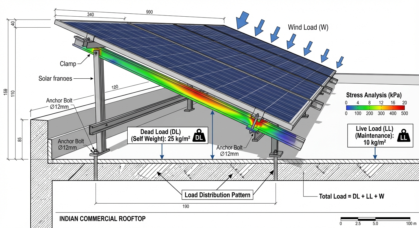
Review the load combination scenarios analyzed in the structural calculations. A comprehensive structural design evaluates multiple load cases:
- Dead load: The weight of solar modules, mounting structures, cables, and other permanent components
- Live load: Temporary loads from maintenance personnel, snow accumulation (in applicable regions), and equipment during installation
- Wind load: Both uplift forces and lateral forces under various wind directions and speeds
- Seismic load: Earthquake forces based on the site’s seismic zone classification (India has four seismic zones)
The structural analysis should consider the worst-case combination of these loads, not just individual load cases. For example, a design might need to withstand dead load plus maximum wind uplift, or dead load plus seismic forces plus partial live load.
Examine the foundation design calculations. For rooftop installations, this includes analysis of the existing roof structure’s capacity to support additional loads. The design should include a roof load assessment that verifies adequate structural capacity, identifies any necessary reinforcement, and specifies appropriate attachment methods. For ground-mount systems, foundation design should account for soil bearing capacity, frost depth (if applicable), and potential settlement issues.
A significant red flag is the use of generic or template structural designs without site-specific calculations. Some designers reuse standard mounting system designs across multiple projects without verifying their adequacy for each site’s unique conditions. This approach may work for similar sites but can lead to failures when conditions differ significantly.
Verify that structural calculations are stamped and signed by a qualified structural engineer. In India, structural engineering India work should be certified by an engineer with appropriate credentials and professional indemnity insurance. This certification provides accountability and assurance that calculations follow accepted engineering practices.
For projects requiring feasibility studies, ensure that structural assessment findings are properly integrated into the final design. Site-specific factors identified during feasibility analysis, such as roof condition issues, soil characteristics, or access constraints, should be reflected in structural design decisions.
Finally, review the level of detail in structural drawings. Quality structural documentation includes:
- Foundation layout plans with dimensions and specifications
- Mounting structure assembly drawings showing all components
- Connection detail drawings for critical joints
- Material specifications including grade and finish requirements
- Installation notes and torque specifications for bolted connections
Incomplete structural drawings force your installation team to make field decisions about critical structural details, increasing the risk of improper installation that compromises system integrity.
4. Cable Sizing and Electrical Optimization
Electrical design quality directly impacts both system performance and project costs. Undersized cables cause excessive voltage drops that permanently reduce energy generation, while oversized cables waste money on unnecessary conductor material. Evaluating cable sizing and electrical optimization reveals whether the designer has properly balanced performance and cost considerations.
Start by reviewing the voltage drop calculations for both DC and AC circuits. Industry best practices recommend limiting voltage drop to:
- DC circuits (module strings to inverter): Maximum 3% voltage drop under full load conditions
- AC circuits (inverter to grid connection point): Maximum 2% voltage drop under full load conditions
- Total system voltage drop: Should not exceed 5% from module output to grid connection
The design should include detailed voltage drop calculations showing cable lengths, conductor sizes, current levels, and resulting voltage drops for each circuit. Be suspicious of designs that specify cable sizes without supporting calculations, as this suggests the designer may be using rules of thumb rather than proper engineering analysis.
Examine the cable routing strategy shown in layout drawings. Efficient cable routing minimizes cable lengths while maintaining proper spacing and protection requirements. Look for evidence that the designer has optimized inverter placement and string configurations to reduce cable runs. Excessive cable lengths not only increase voltage drop but also add unnecessary material costs to the project.
Review the conductor material specifications. For solar applications in India, copper conductors are generally preferred for their superior conductivity and durability, though aluminum conductors may be appropriate for larger AC feeders where cost savings justify the larger conductor sizes required. The design should specify conductor material, insulation type, and temperature rating appropriate for the installation environment.
Check that cable sizing accounts for temperature derating factors. Cable ampacity decreases when ambient temperature exceeds the standard rating temperature (typically 30°C). In India’s hot climate, particularly for cables installed in conduit or cable trays with limited ventilation, temperature derating can significantly reduce cable current-carrying capacity. Quality designs apply appropriate derating factors based on installation method and expected ambient conditions.
Evaluate the string configuration and inverter sizing. The design should optimize the number of modules per string and strings per inverter to maximize energy harvest while staying within equipment specifications. This includes consideration of:
- Module voltage range across operating temperature extremes
- Inverter maximum input voltage and MPPT voltage range
- String current and inverter maximum input current
- Inverter sizing ratio (DC array capacity to inverter AC capacity)
A red flag appears when designs show significant oversizing of cables beyond what voltage drop calculations require. While conservative cable sizing provides a safety margin, excessive oversizing suggests the designer hasn’t properly optimized the electrical design, resulting in unnecessary solar design cost increases.
Conversely, watch for undersized cables that meet voltage drop requirements only under ideal conditions. Quality designs include safety margins that account for real-world variations in solar irradiance, temperature, and equipment performance.
Finally, verify that the design includes proper overcurrent protection and disconnection means at all required locations. This includes DC disconnect switches, AC disconnect switches, circuit breakers, and fuses sized according to equipment specifications and electrical codes. Inadequate protection devices create safety hazards and code compliance issues.
5. Site-Specific Design Adaptations
Generic, template-based designs rarely deliver optimal results. Every solar project site has unique characteristics that should inform design decisions. Evaluating how well a design incorporates site-specific factors reveals whether the designer has invested adequate effort in understanding project requirements.
Begin by verifying that the design incorporates data from a comprehensive site survey India process. A quality site survey documents:
- Accurate site dimensions and available installation area
- Existing structures, obstacles, and potential shading sources
- Roof condition, material, and structural characteristics (for rooftop projects)
- Soil type and bearing capacity (for ground-mount projects)
- Electrical infrastructure and grid connection point location
- Access routes for equipment delivery and installation
- Site photographs documenting existing conditions
The design should demonstrate clear connections between site survey findings and design decisions. For example, if the site survey identified a water tank that creates afternoon shading, the layout should show how module placement accounts for this obstacle.
Examine the shading analysis methodology. Quality designs use 3D modeling tools to simulate shading patterns throughout the year based on actual site conditions. The analysis should identify shading from nearby buildings, trees, parapet walls, and inter-row shading in multi-row arrays. Generic shading assumptions without site-specific analysis often lead to significant overestimation of energy yield.
For ground-mount projects, verify that the design accounts for terrain characteristics. Sloped sites require different mounting approaches than flat sites. Drainage patterns should be considered to prevent water accumulation around foundations. Vegetation management requirements should be documented based on local conditions.
Review how the design addresses local climate factors beyond basic irradiation data. India’s diverse climate zones present different design challenges:
- Coastal regions: High humidity and salt exposure require corrosion-resistant materials and protective coatings
- Desert regions: Extreme temperatures and dust accumulation necessitate appropriate module selection and cleaning strategies
- High-rainfall areas: Drainage design and waterproofing become critical considerations
- Mountainous regions: Snow loads and high wind exposure may require reinforced structures
A red flag appears when designs show identical layouts and specifications across multiple projects in different locations. While certain design elements may be standardized, quality designs demonstrate site-specific adaptations that optimize performance and reliability for each project’s unique conditions.
Check that the design incorporates findings from any feasibility study India work performed during project development. Feasibility studies identify site constraints, grid connection requirements, and economic optimization opportunities that should inform detailed design decisions. Disconnect between feasibility findings and final design suggests inadequate coordination or rushed design work.
Finally, evaluate whether the design accounts for site access and constructability. A design that looks good on paper but proves difficult to build creates costly field problems. Quality designs consider equipment delivery routes, crane access requirements, staging areas, and installation sequence. Designers with field experience incorporate constructability considerations that smooth the installation process.
6. Documentation Completeness and Quality
Complete, clear documentation is the hallmark of quality solar design work. Your installation team relies on design documents to understand what to build and how to build it. Incomplete or ambiguous documentation leads to field questions, delays, and potential errors that compromise project quality.
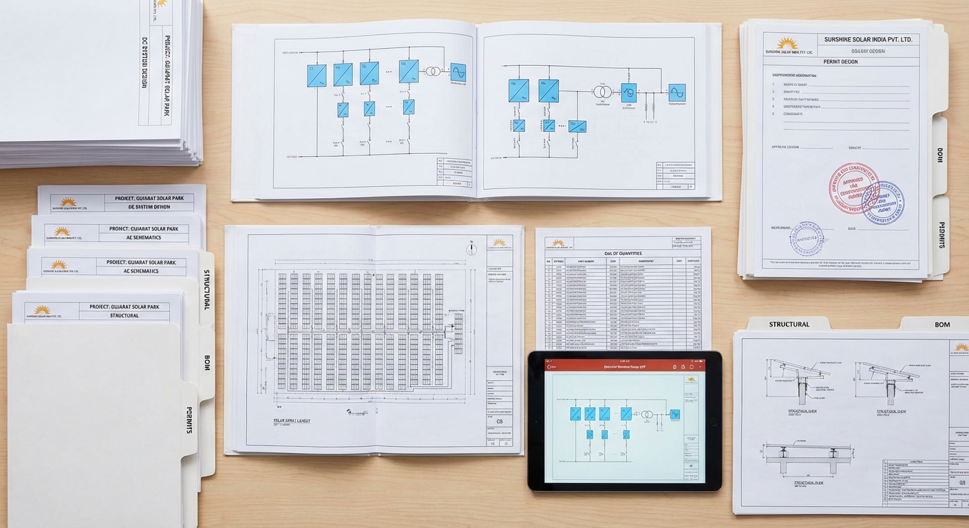
A complete solar design package should include the following core documents:
Electrical Documentation
- Single line diagram (SLD): Shows the complete electrical system from solar array through inverters to grid connection, including all protection devices, disconnects, and metering
- Three line diagram: Details three-phase AC wiring with proper phase identification
- String wiring diagrams: Shows how modules are connected into strings and how strings connect to inverters
- AC and DC cable schedules: Lists all cables with specifications, lengths, and routing information
- Equipment schedules: Complete specifications for modules, inverters, transformers, and other electrical equipment
- Earthing and lightning protection drawings: Shows grounding system design and lightning protection measures
Structural Documentation
- Foundation layout plans: Shows location and specifications for all foundations
- Mounting structure drawings: Assembly drawings for module mounting systems
- Structural calculations: Load analysis and member sizing calculations
- Connection details: Detailed drawings of critical structural connections
Layout and General Arrangement
- Site layout plan: Overall project layout showing all major components
- Module layout drawings: Precise placement of all solar modules
- Equipment layout: Location of inverters, transformers, switchgear, and other equipment
- Cable routing plans: Shows cable tray routes, conduit runs, and trenching requirements
Specifications and Schedules
- Bill of quantities (BOQ): Complete material quantities for procurement
- Technical specifications: Detailed specifications for all equipment and materials
- Installation specifications: Instructions for proper installation procedures
For projects requiring regulatory approval, verify that the package includes all permit design documents required by local authorities. Permit requirements vary by location but typically include electrical drawings, structural calculations, site plans, and equipment specifications formatted according to authority requirements.
Evaluate the clarity and professionalism of the documentation. Quality drawings include:
- Clear title blocks with project information, drawing numbers, and revision tracking
- Appropriate scale and level of detail for the drawing purpose
- Legible text and dimension annotations
- Consistent symbols and notation throughout the drawing set
- Notes and legends explaining symbols and abbreviations
- Proper layering and organization in CAD files
A red flag appears when drawings lack basic information like scales, dimensions, or equipment specifications. Incomplete drawings force your team to make assumptions or request clarifications, slowing project progress and increasing the risk of errors.
Check for consistency across documents. Equipment specifications in the single line diagram should match the equipment schedule and BOQ. Cable sizes shown in drawings should match the cable schedule. Inconsistencies suggest rushed or poorly coordinated design work and create confusion during procurement and installation.
Verify that the documentation includes design calculations and assumptions. While detailed calculations may be in separate reports, the drawing set should reference these calculations and summarize key assumptions. This allows you to verify the engineering basis for design decisions and provides documentation for future reference.
Finally, assess whether the documentation is construction-ready. Can your installation team use these drawings to build the project without constant designer involvement? Quality documentation anticipates field questions and provides sufficient detail for competent installers to execute the work correctly.
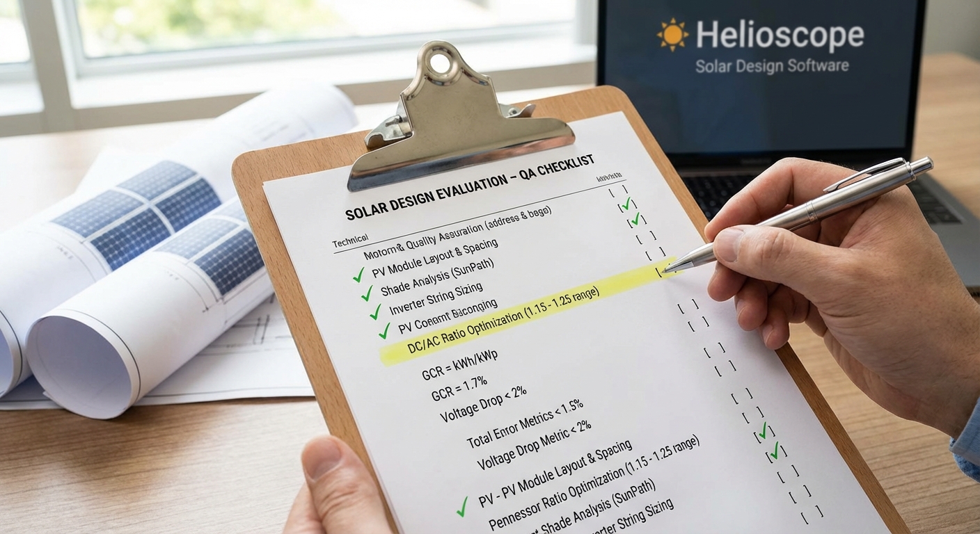
7. Design Software and Methodology Verification
The tools and methods used to create a solar design significantly impact its quality and reliability. While software doesn’t guarantee quality design, the use of industry-standard tools and validated methodologies provides confidence that the design follows established best practices.
Verify that the designer uses recognized design software India tools appropriate for each design discipline:
Energy Modeling Software
- PVsyst: Industry-standard tool for detailed energy yield modeling with validated loss models
- Helioscope: Cloud-based design platform with integrated shading analysis and financial modeling
- PVWatts: NREL’s simplified calculator suitable for preliminary estimates
- SAM (System Advisor Model): Comprehensive modeling tool for detailed performance and financial analysis
Electrical Design Software
- AutoCAD Electrical: Professional electrical CAD with built-in electrical symbols and standards
- ETAP or SKM PowerTools: Power system analysis for larger projects requiring load flow and protection coordination studies
Structural Design Software
- STAAD.Pro: Structural analysis software widely used in India for load analysis and member design
- SAP2000: Advanced structural analysis for complex structures
- Manufacturer-specific tools: Many mounting system manufacturers provide design tools validated for their products
3D Modeling and Visualization
- SketchUp: 3D modeling for layout visualization and shading analysis
- AutoCAD or Revit: Professional CAD platforms for detailed design documentation
Request information about software versions and licensing. Using outdated software versions may mean missing important updates, bug fixes, or new features. Unlicensed software raises serious concerns about the designer’s professionalism and the validity of design outputs, as unlicensed versions may lack technical support and validation.
Beyond software tools, evaluate the design methodology employed. Quality designers follow systematic processes:
- Requirements gathering: Understanding project goals, constraints, and client requirements
- Preliminary design: Developing initial concepts and layouts for review
- Detailed design: Creating comprehensive documentation with full calculations
- Design review: Internal quality checks before delivery
- Revision management: Systematic tracking and incorporation of changes
Ask about the designer’s quality assurance processes. Reputable design firms implement internal review procedures where senior engineers check work before delivery. This peer review process catches errors and ensures consistency with firm standards.
Verify that critical calculations include manual verification or cross-checks. While software automates many calculations, quality engineers verify key results through manual calculations or alternative methods. This catches software input errors or misapplication of tools.
A red flag appears when designers cannot clearly explain their methodology or provide calculation backup. If a designer claims results are “from the software” without understanding the underlying calculations, they may be operating the tools without adequate engineering judgment.
For EPCs working with a design partner, evaluate their investment in tools and training. Firms that invest in professional software licenses, ongoing training, and process improvement demonstrate commitment to quality. Those cutting corners on tools and training likely cut corners in design work as well.
8. Cost Optimization Without Compromising Quality
The final indicator of design quality is the designer’s ability to optimize costs while maintaining performance and reliability standards. A quality design maximizes value, delivering required performance at the lowest reasonable cost, rather than simply minimizing first cost without regard to long-term implications.
Evaluate whether the design demonstrates value engineering thinking. Value engineering systematically examines design decisions to identify opportunities for cost reduction without sacrificing essential functions. Examples include:
- Inverter selection: Choosing appropriately sized inverters rather than oversizing unnecessarily
- Module selection: Balancing module efficiency, cost, and reliability for the specific application
- Mounting system optimization: Selecting mounting solutions appropriate for site conditions rather than over-engineering
- Cable routing efficiency: Minimizing cable runs through smart layout and equipment placement
- Foundation design: Right-sizing foundations based on actual loads rather than using conservative generic designs
A quality design should include documentation of optimization decisions. For significant choices, the designer should explain the alternatives considered and the rationale for the selected approach. This demonstrates thoughtful engineering rather than default selections.
Be cautious of designs with unrealistically low solar design cost estimates. While competitive pricing is important, extremely low design fees often correlate with rushed work, inexperienced designers, or inadequate scope. The old adage applies: you get what you pay for. Investing in quality design upfront typically saves far more than the design fee through optimized procurement, reduced rework, and better long-term performance.
Conversely, watch for unnecessary gold-plating where designs specify premium components or over-engineered solutions without justification. Some designers default to conservative, expensive approaches rather than optimizing for the specific project requirements. This inflates engineering cost and project cost without corresponding benefits.
Evaluate the balance between standardization and customization. Standardized design elements reduce engineering time and leverage proven solutions, lowering design costs. However, every project requires some customization for site-specific conditions. Quality designers know when to apply standard approaches and when customization adds value.
Review the bill of quantities (BOQ) for optimization opportunities. A detailed BOQ allows you to identify cost drivers and evaluate alternatives. For example, if cable costs represent a significant portion of the budget, you might explore layout modifications that reduce cable runs. Quality designers provide BOQs with sufficient detail to support this analysis.
Consider the total cost of ownership, not just first cost. A design that saves money on initial equipment but results in higher maintenance costs or lower energy production may prove more expensive over the project lifetime. Quality designs consider lifecycle costs and optimize for long-term value.
Finally, assess whether the design supports efficient construction. Designs that are difficult to build increase labor costs and schedule duration. Quality designers with field experience create designs that are not only technically sound but also practical to construct, reducing overall project costs.
Implementing a Design Quality Checklist for Your EPC Company
Understanding these eight technical indicators is just the first step. To consistently evaluate design quality across all your projects, implement a systematic evaluation framework within your EPC organization.
Start by creating a standardized design quality checklist based on the indicators discussed in this guide. Your checklist should include specific items to verify for each indicator, with clear pass/fail criteria or scoring rubrics. This standardization ensures consistent evaluation regardless of who performs the review.
Assign clear roles and responsibilities for design review. Typically, this involves:
- Project manager: Overall responsibility for design approval and schedule coordination
- Electrical engineer: Review of electrical design, calculations, and documentation
- Structural engineer: Review of structural design and calculations
- Procurement team: Review of BOQ accuracy and specifications
- Construction manager: Review of constructability and completeness
Establish a design review timeline that balances thoroughness with project schedule requirements. While comprehensive review takes time, catching design issues before construction begins saves far more time than addressing problems in the field. A typical review timeline might include:
- Preliminary design review: 3-5 days for initial concept approval
- Detailed design review: 7-10 days for comprehensive evaluation
- Final design approval: 2-3 days for sign-off after revisions
For complex or high-value projects, consider engaging PMC services India providers for independent design review. Third-party review by experienced consultants provides an additional quality check and can identify issues your internal team might miss. This is particularly valuable when working with new design partners or tackling unfamiliar project types.
Develop feedback mechanisms with your design partners. When you identify design issues, communicate them clearly and work collaboratively toward solutions. Quality design partners appreciate constructive feedback and use it to improve their processes. If a design partner consistently fails to meet quality standards despite feedback, it may be time to seek alternatives.
Track design quality metrics over time to identify trends and improvement opportunities:
- Number of design revisions required before approval
- Field change orders resulting from design issues
- Actual vs. predicted energy yield for completed projects
- Design-related delays in project schedule
- Cost of design-related rework during construction
These metrics help you evaluate design partner performance, justify investment in quality design, and identify areas where your review process needs strengthening.
Invest in training for your review team. As solar technology and standards evolve, your team needs ongoing education to maintain evaluation competence. This might include attending industry conferences, participating in technical training programs, or bringing in expert consultants for knowledge transfer sessions.
Finally, recognize that design quality evaluation is an investment in project success. The time and resources spent on thorough design review pay dividends through smoother construction, better performance, and satisfied clients. EPCs that master design quality evaluation build reputations for excellence that drive business growth and profitability.
Partner with Design Quality Experts
Evaluating design quality requires expertise, time, and systematic processes. For many solar EPC India companies, partnering with a specialized design firm that consistently delivers high-quality work proves more efficient than building extensive in-house design capabilities.
Heaven Designs Private Limited has built a reputation for design quality excellence across 752+ solar projects totaling 628+ MW. Our team of 50+ skilled engineers and consultants understands the technical indicators that matter to EPCs because we’ve worked alongside installation teams to see how design decisions impact field execution.
When you partner with Heaven Designs, you receive designs that pass rigorous quality checks before delivery. Our systematic design process incorporates the eight technical indicators discussed in this guide, ensuring that every project meets the highest standards for accuracy, compliance, and completeness. From precise energy yield calculations using industry-standard software to comprehensive structural engineering India expertise, we deliver construction-ready documentation that minimizes field questions and change orders.
Our services span the complete design lifecycle, from initial site survey India and feasibility studies through detailed engineering design and permit design preparation. Whether you’re developing rooftop solar installations, ground-mount commercial projects, or megawatt-scale solar farms, our team has the expertise to optimize design quality while controlling costs.
We understand that design quality directly impacts your project success and reputation. That’s why we invest in professional design software India tools, maintain rigorous internal quality review processes, and stay current with evolving standards and best practices. Our designs don’t just meet minimum requirements, they demonstrate the engineering excellence that sets successful projects apart.
Ready to ensure your next solar project is built on a foundation of quality design? Get a Quick Proposal Now! or contact our team at +91 90811 00297 or service@heavendesigns.in to discuss how our design quality expertise can support your project success. Let’s work together to deliver solar installations that exceed client expectations and maximize long-term performance.
This blog post was written using thestacc.com