
For solar EPC companies in India, the difference between a profitable project and a costly disaster often comes down to one critical factor: design accuracy. A single miscalculation in structural loads, an oversight in shading analysis, or an error in electrical sizing can lead to installation delays, safety hazards, budget overruns, and damaged client relationships. As the solar industry continues its rapid expansion across India and global markets, the stakes for getting designs right the first time have never been higher.
This comprehensive guide walks you through nine essential technical checks that every solar EPC company must perform to verify design accuracy before breaking ground on installation. Whether you’re working on rooftop solar India projects or megawatt-scale ground mount installations, these validation methods will help you catch errors early, protect your margins, and deliver projects that perform as promised.
Why Design Accuracy Matters for Solar EPC Companies
The financial and operational consequences of poor design accuracy extend far beyond simple rework costs. When solar engineering designs contain errors, EPC companies face a cascade of problems that can threaten project viability and company reputation.

Financial impact is often the most immediate concern. Design errors discovered during installation can require emergency redesigns, component reordering, and extended labor costs. A structural miscalculation might mean reinforcing a rooftop at unexpected expense. An electrical sizing error could necessitate replacing inverters or reconfiguring entire string layouts. These corrections typically cost three to five times more than getting the design right initially.
Beyond direct costs, project timeline delays create ripple effects throughout your business. Delayed commissioning means delayed payments, tied-up working capital, and potential penalty clauses. Your installation crews sit idle or must be reassigned, disrupting schedules for other projects. Clients lose confidence, and your reputation in the competitive solar EPC India market suffers.
Safety and structural risks represent the most serious consequences of design inaccuracy. Underestimated wind loads can lead to module failures during storms. Inadequate structural assessments may result in roof damage or collapse. Electrical design errors can create fire hazards or electrocution risks. These scenarios expose your company to liability, regulatory action, and potential loss of licenses.
Regulatory compliance issues stemming from inaccurate feasibility studies or permit designs can halt projects entirely. State electricity boards and local authorities in India have become increasingly stringent about documentation accuracy. A rejected permit application means weeks of delays and the cost of redesign and resubmission.
For these reasons, implementing rigorous design accuracy verification processes isn’t optional—it’s essential for sustainable business operations. The following nine technical checks provide a systematic approach to catching errors before they become expensive problems.
1. Energy Yield Calculation Verification
Energy yield predictions form the financial foundation of every solar project. Clients make investment decisions based on these numbers, and overestimated yields can lead to disappointed customers and contract disputes. Verifying the accuracy of energy calculations should be your first technical checkpoint.
Cross-check simulation software outputs by running the same project through multiple tools. If you primarily use PVsyst, validate key results with PVWatts, Helioscope, or other solar design software India platforms. Discrepancies larger than 5-8% between tools warrant investigation. The differences often reveal input errors, incorrect weather data, or modeling assumptions that need adjustment.
Validate your solar irradiation data sources carefully. Many design errors stem from using generic weather data instead of site-specific measurements. For projects in India, compare data from multiple sources such as NREL, Meteonorm, and NASA SSE databases. Ground-mounted weather stations or satellite-derived data specific to your project location provide the most reliable inputs. Be particularly cautious with projects in areas with unique microclimates or high pollution levels that affect irradiation.
Understand acceptable tolerance levels for energy predictions. Industry best practices suggest that annual energy yield estimates should fall within ±5-8% of actual performance for well-designed systems. Predictions claiming accuracy better than ±5% are unrealistic given weather variability and modeling limitations. If your calculations show significantly higher yields than industry benchmarks for similar systems in the same region, revisit your assumptions.
Red flag indicators include performance ratios above 85% without compelling justification, capacity utilization factors that exceed regional norms by more than 10%, or degradation rates below 0.5% annually. These optimistic assumptions may make project economics look attractive but set unrealistic client expectations. A professional solar design process builds in conservative assumptions that protect both you and your client.
Compare your energy yield calculations against actual performance data from similar completed projects in your portfolio. This historical validation provides the most reliable accuracy check and helps you refine your modeling approach over time.
2. Structural Load Assessment Review
Structural failures represent some of the most dangerous and expensive consequences of design inaccuracy. Every solar installation must withstand decades of environmental stresses, making thorough structural validation non-negotiable.
For rooftop solar India installations, verify that wind load calculations follow IS 875 Part 3 standards appropriate for the project location. India’s diverse geography means wind zones vary significantly from coastal areas to inland regions. Confirm that the design uses the correct basic wind speed for the site’s wind zone, applies appropriate terrain and height factors, and includes proper safety margins. Rooftop installations face additional complexity from parapet walls, building height, and roof edge effects that amplify wind forces.
Dead load and live load calculations must account for the complete system weight plus maintenance access requirements. Dead loads include modules, mounting structures, cables, and any ballast systems. Don’t forget to include the weight of accumulated dust, which can be substantial in certain Indian regions. Live loads must accommodate maintenance personnel and equipment access. For rooftop projects, verify that the existing structure can handle these additional loads without reinforcement.
Structural engineering India requirements mandate specific safety factors and design approaches. Confirm that calculations include appropriate factors of safety (typically 1.5 for dead loads and 2.5 for live loads). For ground mount systems, foundation designs must consider soil bearing capacity, frost depth where applicable, and seismic requirements based on the site’s seismic zone.
Red flags in structural design include missing seismic zone considerations, generic structural calculations not specific to the actual building or site, absence of a licensed structural engineer’s stamp on drawings, or mounting systems specified without manufacturer load ratings. Any rooftop project that doesn’t include a structural assessment of the existing building should be rejected immediately.
For ground mount projects, verify that foundation designs match actual soil conditions from geotechnical reports. Assumptions about soil bearing capacity without testing often lead to foundation failures or expensive over-engineering.
3. Electrical Sizing and Configuration Validation
Electrical design errors create safety hazards, reduce system performance, and can render entire installations non-functional. Thorough validation of electrical sizing and configuration protects your project from these critical failures.
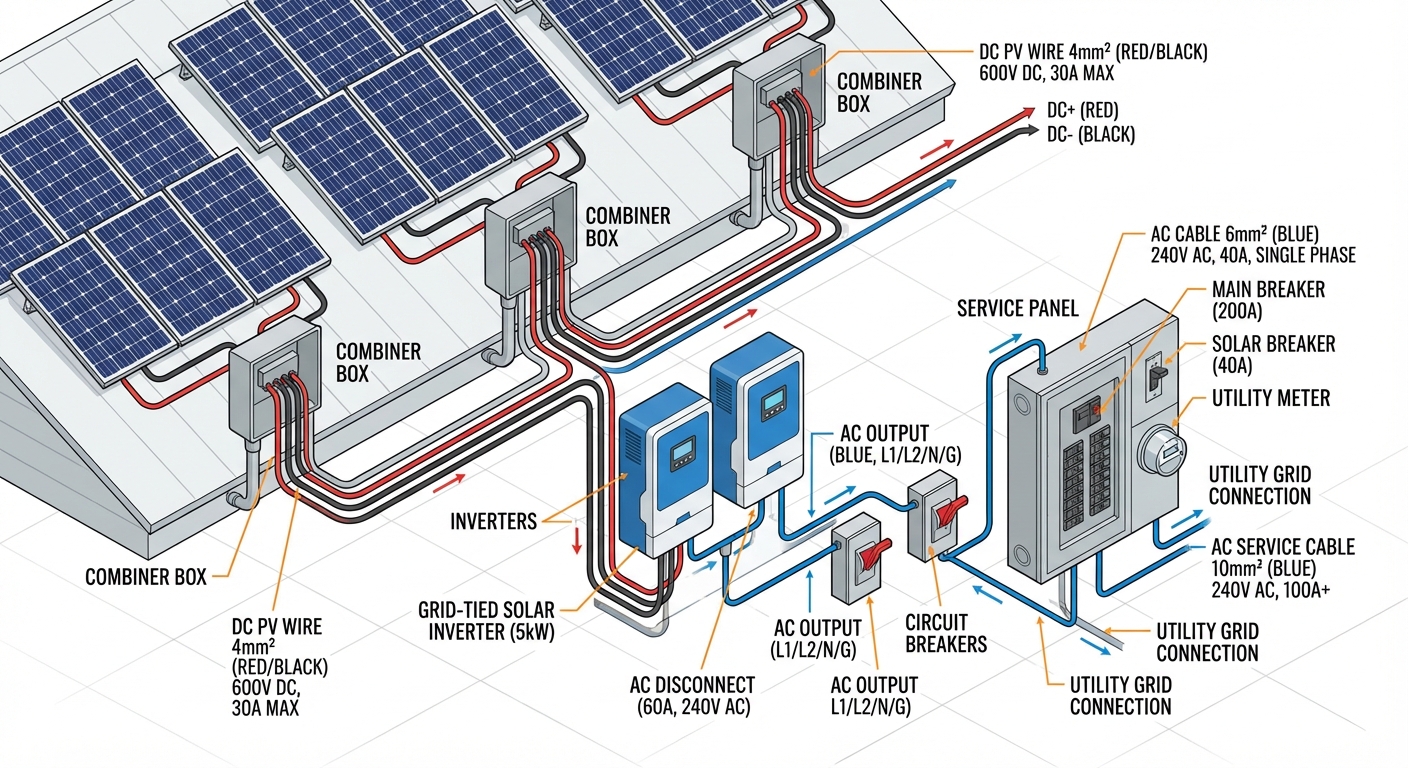
String sizing calculations must respect the voltage and current limits of all system components. Verify that string voltages remain within inverter input ranges across the full temperature range expected at the site. Cold morning temperatures increase voltage, while hot afternoons reduce it. Strings that work fine at 25°C may exceed inverter limits at -10°C or fall below minimum operating voltage at 70°C module temperatures. Calculate voltage drop across DC cables and confirm it stays below 3% under maximum current conditions.
The inverter-to-module ratio, also called DC:AC ratio or inverter loading ratio, significantly impacts system economics and performance. Ratios between 1.1 and 1.3 are common for most Indian locations, allowing some overloading to capture energy during morning and evening hours while accepting minor clipping during peak sun. Ratios below 1.0 suggest undersized arrays that won’t fully utilize inverter capacity. Ratios above 1.4 may cause excessive clipping losses. Verify that the chosen ratio makes sense for the site’s irradiation profile and project economics.
Cable sizing adequacy requires checking both current carrying capacity and voltage drop. AC and DC cables must handle maximum expected currents with appropriate derating factors for temperature, bundling, and installation method. Undersized cables create fire hazards and efficiency losses. Verify that cable specifications include proper insulation ratings for DC applications (solar cables rated for 1500V DC for systems above 1000V) and UV resistance for outdoor routing.
Protection device ratings and coordination ensure safe system operation under fault conditions. Confirm that fuses or circuit breakers are properly sized for cable protection, that DC disconnects have adequate voltage and current ratings, and that surge protection devices are specified for the system voltage. Grounding and earthing design must comply with IS 3043 standards and local electrical codes.
Red flags in electrical design include generic cable specifications without specific sizing calculations, missing or improperly rated protection devices, string configurations that violate inverter specifications, or absence of single-line diagrams showing complete system architecture. Any design lacking proper grounding details should be rejected as incomplete and potentially dangerous.
4. Shading Analysis Accuracy Check
Shading losses often represent the largest gap between predicted and actual system performance. Even small shading errors in design can lead to significant energy yield discrepancies and client dissatisfaction.
Validate that 3D modeling accuracy reflects actual site conditions captured during the site survey India process. Compare the 3D model against site photographs and survey measurements. Check that all obstructions are modeled with correct heights, positions, and dimensions. Common missed items include HVAC equipment, exhaust vents, communication antennas, neighboring buildings, trees, and parapet walls.
Distinguish between near-shading and far-shading impacts. Near shading from objects close to the array (within a few meters) creates hard shadows with sharp edges that can completely shade individual modules or cells. Far shading from distant objects creates softer, more diffuse shadows. Both types affect performance differently, and accurate modeling requires proper representation of each. Verify that the shading analysis accounts for the specific shading response of the modules being used—some module technologies handle partial shading better than others.
Seasonal shading pattern verification is critical for accurate annual energy predictions. A site that appears unshaded during a summer survey may experience significant winter shading when the sun angle is lower. Run shading simulations for multiple times throughout the year, not just the survey date. Pay special attention to morning and evening hours when sun angles are low and shadows are longest.
Tools for shading validation include on-site measurements with solar pathfinders or shading analyzers, drone photography for accurate 3D modeling, and cross-checking between different software platforms. Ground-mounted projects should include analysis of inter-row shading throughout the day and year.
Red flags include shading analysis based solely on satellite imagery without site verification, missing obstructions visible in site photos, unrealistic shading loss percentages below 2% for complex rooftops, or analysis that doesn’t account for future construction or tree growth mentioned in site reports.
5. Module Layout and Spacing Verification
Optimizing module layout requires balancing maximum capacity with practical installation and maintenance requirements. Poor layout decisions reduce energy generation, create safety issues, and complicate installation.
For ground mount India projects, verify row-to-row spacing calculations using proper solar geometry for the site latitude. The spacing must prevent inter-row shading during peak generation hours, typically calculated to avoid shading at 9 AM on the winter solstice. Insufficient spacing reduces energy yield, while excessive spacing wastes land and increases balance-of-system costs. Confirm that calculations account for module tilt angle, mounting height, and local latitude.
Walkway and maintenance access requirements must be incorporated into layouts. Fire codes typically require perimeter access paths, and maintenance needs dictate spacing for cleaning equipment and personnel movement. For rooftop installations, verify that layouts include required setbacks from roof edges, adequate spacing around roof penetrations and equipment, and access paths to all roof areas. Layouts that maximize capacity by eliminating access space create operational problems and may violate fire safety codes.
Fire safety clearances vary by jurisdiction but typically include requirements for roof access paths, equipment access zones, and smoke ventilation areas. In India, National Building Code and local fire department requirements may mandate specific clearances. Verify that the layout complies with all applicable codes. Non-compliant layouts will be rejected during permit review or final inspection.
Optimize designs for maximum capacity within constraints by using appropriate module orientations (portrait vs. landscape), minimizing unusable gaps, and efficiently arranging strings to reduce wiring losses. However, never sacrifice code compliance or practical installation requirements for marginal capacity gains.
Red flags include layouts with no maintenance access paths, row spacing that will cause shading during morning or evening hours, missing fire safety setbacks, or arrangements that make installation extremely difficult (such as requiring installers to work in confined spaces or at dangerous heights without proper access).
6. Compliance Documentation Review
Even technically perfect designs fail if they don’t meet regulatory requirements. Compliance documentation review ensures your project will pass permitting and inspection processes without delays.
Permit design requirements vary significantly across different states in India. Each state electricity board has specific technical standards, documentation formats, and approval processes. Verify that your design package includes all required documents in the correct format: single-line diagrams, layout drawings, equipment specifications, structural calculations, and any state-specific forms. Missing or incorrectly formatted documents will delay approval.
CEA regulations and MNRE guidelines establish national standards for grid-connected solar systems. Confirm that equipment specifications meet CEA technical standards for solar PV systems, that protection schemes comply with CEA connectivity regulations, and that the design follows MNRE guidelines for the applicable program (if seeking subsidies or incentives). Using non-approved equipment or non-compliant designs will result in rejection.
Local authority requirements add another layer of compliance. Municipal building departments may require structural approvals, fire department clearances, and zoning compliance verification. Some areas have additional requirements for heritage zones, airport proximity, or environmental sensitivity. Research all applicable local requirements early in the design process.
For net metering applications, verify that documentation accuracy matches utility requirements exactly. Incorrect meter specifications, missing protection device details, or discrepancies between drawings and application forms cause rejections. Many utilities require specific calculation formats or certification stamps from licensed engineers.
Red flags include missing professional engineer stamps on structural or electrical drawings, references to outdated standards or codes, equipment specifications that don’t match approved model lists, or generic designs not customized for the specific jurisdiction’s requirements. Any design that hasn’t been reviewed against current local regulations should be considered incomplete.
7. Bill of Materials (BOM) Cross-Verification
The bill of materials bridges design and procurement, making BOM accuracy critical for project execution. Errors here lead to procurement delays, budget overruns, and installation problems.
Verify that component specifications match design requirements exactly. Module specifications should match the model used in energy calculations and structural analysis. Inverter specifications must align with electrical design parameters. Mounting structure specifications should reflect structural engineering calculations. Discrepancies between design documents and BOM specifications will cause problems during installation or performance verification.
Quantity verification requires careful cross-checking against layout drawings. Count modules in the layout and compare to BOM quantities. Calculate required cable lengths from routing drawings and verify against BOM. Check that quantities include appropriate spare factors (typically 2-5% for small components like connectors and fasteners). Under-ordering causes project delays, while over-ordering wastes budget.
Confirm compatible component selections across the system. Verify that connectors match module and inverter specifications, that mounting hardware is compatible with the specified structure and module frames, and that all electrical components have matching voltage and current ratings. Incompatible components discovered during installation create expensive emergency procurement situations.
Solar design cost accuracy depends heavily on BOM precision. Verify that component specifications in the BOM match pricing assumptions in project budgets. Substituting higher-cost components during procurement without design review can eliminate project margins. Conversely, value engineering opportunities may exist if equivalent lower-cost components can meet design requirements.
Red flags include generic component descriptions without specific model numbers, quantities that don’t match drawing counts, missing items like cables or connectors, or specifications that don’t match manufacturer data sheets. Any BOM that hasn’t been cross-verified against complete design drawings should be considered unreliable for procurement.
8. Site Conditions vs Design Assumptions
Design assumptions must align with actual site conditions, or the installation will encounter unexpected problems. This validation check catches discrepancies between design models and physical reality.
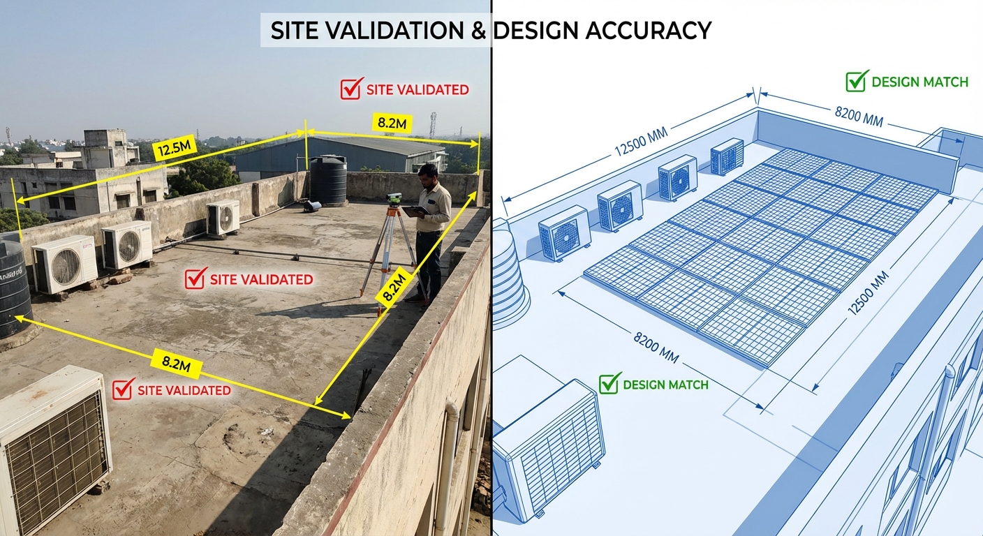
Compare design parameters to actual site survey data systematically. Verify that roof dimensions in the design match measured dimensions from the survey. Check that assumed roof orientations and tilt angles reflect actual conditions. Confirm that electrical service characteristics (voltage, phase, available capacity) match utility documentation. Any assumptions not validated by survey data represent risks that may materialize during installation.
Soil conditions for foundation design must come from actual geotechnical testing, not assumptions. For ground mount projects, verify that foundation designs use soil bearing capacity, soil type, and groundwater levels from site-specific soil reports. Generic foundation designs based on assumed soil conditions often prove inadequate or unnecessarily expensive when actual conditions differ.
Verify grid connection point and voltage level details against utility documentation. Confirm the exact location of the interconnection point, available fault current levels for protection device sizing, and any utility-specific technical requirements. Assumptions about grid characteristics without utility verification lead to redesign during interconnection approval.
Access and logistics considerations affect installation feasibility and cost. Verify that the design accounts for actual site access constraints: road width for equipment delivery, crane access for rooftop lifts, material staging areas, and any restrictions on working hours or noise. Designs that ignore logistics realities create installation delays and cost overruns.
Red flags include designs based on satellite imagery without site verification, assumptions about structural capacity without engineering assessment, electrical designs that don’t reference actual utility interconnection studies, or layouts that ignore access constraints documented in site reports. Any design assumption not validated by a thorough feasibility study should be questioned.
9. Drawing Set Completeness and Consistency
Complete, consistent drawing packages enable smooth installation and prevent costly field confusion. This final check ensures your documentation is ready for construction.
Verify complete drawing package delivery including all required disciplines. A complete set typically includes: site plan, module layout plan, mounting structure details, electrical single-line diagram, AC and DC wiring diagrams, grounding plan, conduit routing plan, inverter and equipment layout, structural details and calculations, and installation notes. Missing drawings force installers to make field decisions that may not align with design intent.
Cross-reference between drawing sheets to catch inconsistencies. Module quantities on the layout plan should match the electrical diagram and BOM. Cable sizes on wiring diagrams should match specifications on the cable schedule. Equipment locations should be consistent across all relevant drawings. Inconsistencies create confusion and installation errors.
Verify revision control and version consistency across the drawing set. All sheets should show the same revision number and date. Outdated sheets mixed into the package lead to installations based on superseded designs. Implement a clear revision tracking system that identifies what changed in each revision.
Assess clarity and constructability from an installer’s perspective. Drawings should include sufficient detail for installation without ambiguity. Dimensions, specifications, and installation notes should be clear and complete. Complex details should include enlarged views or sections. Drawings that require extensive interpretation or leave critical details undefined will cause field problems.
Red flags include missing drawing sheets from the set, conflicting information between drawings (such as different cable sizes specified in different locations), missing revision information, unclear or ambiguous details, or drawings that lack professional formatting and organization. Any drawing set that hasn’t been reviewed for completeness and consistency by a senior solar engineer should not be released for construction.
Implementing a Design Accuracy Verification Process
Systematic verification processes transform these nine technical checks from good intentions into consistent practice. Implementing structured quality assurance protects your projects and builds organizational capability.
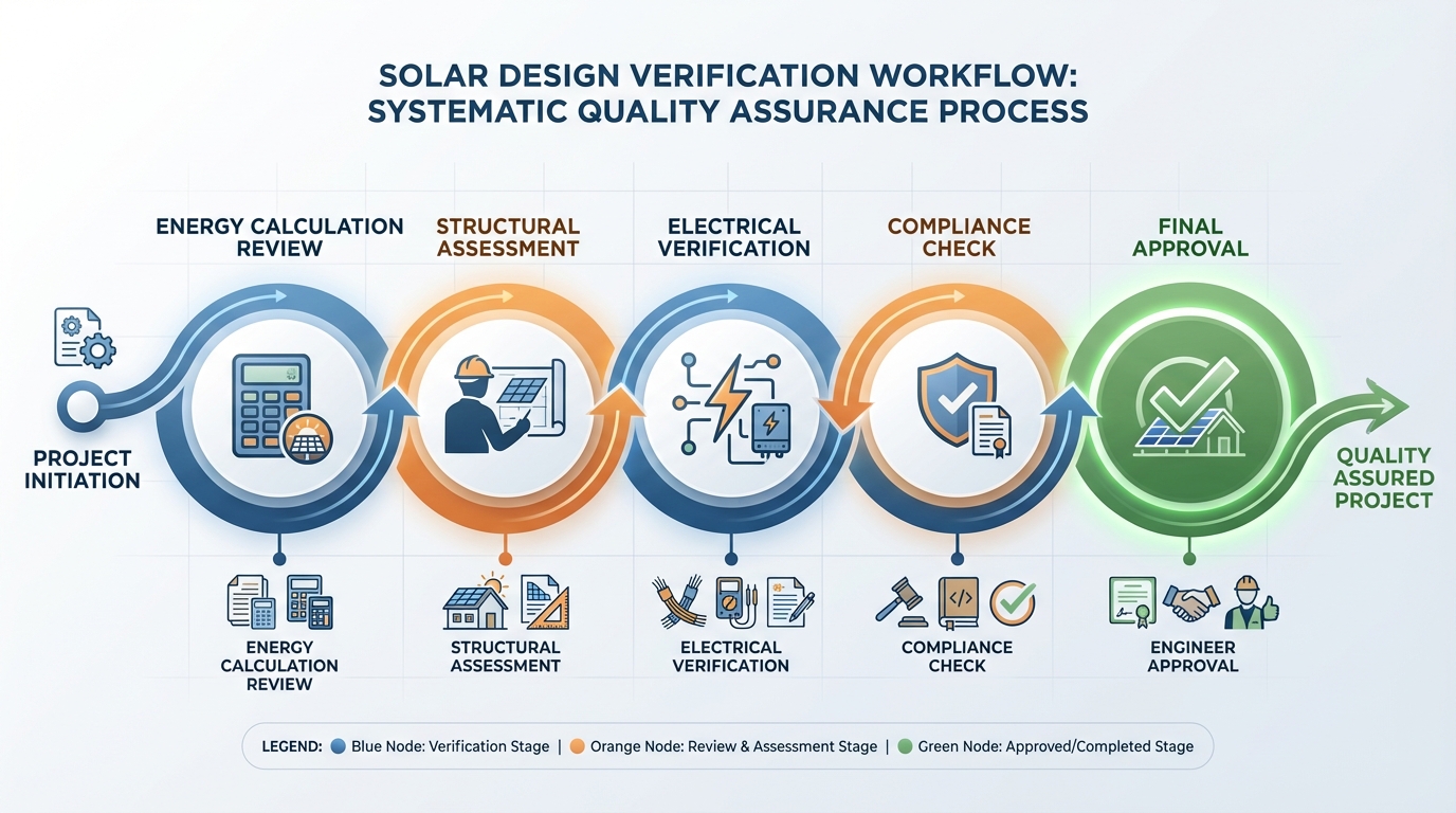
Create a standardized checklist that documents each verification step for every project. The checklist should include specific criteria for each of the nine technical checks, space for reviewer notes and signatures, and clear pass/fail criteria. Standardization ensures consistent quality regardless of which solar engineer performs the review and creates documentation for future reference.
Establish review stages in your design timeline that align with project milestones. Typical stages include preliminary design review (30% complete), detailed design review (90% complete), and final pre-construction review (100% complete). Each stage should have defined deliverables and verification requirements. Building verification into your workflow prevents last-minute discoveries of major issues.
Define the role of design partners in your quality assurance process. If you work with external design consultancies, clarify verification responsibilities in your agreements. Professional design services should include internal quality checks before delivery, but EPC companies retain ultimate responsibility for design accuracy. Consider whether your design partner provides independent verification or if you need additional review resources.
For large or complex projects, consider engaging PMC services India providers for independent design verification. Third-party review by experienced consultants catches issues that internal teams may overlook and provides additional assurance for high-stakes projects. PMC services can be particularly valuable for new project types or technologies where your team has limited experience.
Implement clear documentation and sign-off procedures that create accountability. Each verification checklist should be signed by the reviewing engineer and approved by a senior technical authority before the design is released for construction. Maintain records of all verification activities for quality management and potential future reference.
Invest in training your team on verification procedures and common error patterns. Regular review of lessons learned from past projects helps prevent recurring issues. As your team gains experience with systematic verification, design accuracy improves and verification becomes more efficient.
Common Design Accuracy Pitfalls in Solar EPC Projects
Understanding common failure patterns helps you focus verification efforts where problems most often occur. These pitfalls appear repeatedly across the solar EPC India industry.
Rushing through the design phase to meet aggressive project timelines creates the most design errors. When sales teams promise unrealistic delivery schedules, design teams cut corners on verification to meet deadlines. This pressure leads to skipped calculations, unverified assumptions, and incomplete documentation. The time saved in design is lost many times over during installation when errors are discovered. Protect design quality by establishing realistic timelines that include proper verification time.
Over-reliance on automated design software India tools without understanding underlying calculations causes subtle errors. Software tools are powerful but not infallible. They depend on correct inputs and appropriate modeling assumptions. Blindly accepting software outputs without sanity checks or manual verification of critical calculations leads to propagated errors. Use software as a tool, but maintain engineering judgment and verification practices.
Inadequate site surveys create the foundation for design errors. Site visits that miss critical details, rely too heavily on satellite imagery, or fail to document site constraints lead to designs based on incorrect assumptions. The cost of thorough site surveys is minimal compared to the cost of design errors they prevent. Never compromise on site survey quality to save time or money.
Communication gaps between design and installation teams result in designs that are technically correct but practically difficult to build. Designers who don’t understand installation realities may create layouts that are impossible to build efficiently or safely. Regular communication between design and field teams, including design reviews with installation input, prevents these issues.
Professional design services from experienced providers help avoid these pitfalls through established processes, experienced teams, and systematic quality assurance. When evaluating design partners, assess their verification procedures and quality track record, not just their design software capabilities or pricing.
Design accuracy verification isn’t just a quality control exercise—it’s a competitive advantage. EPC companies that consistently deliver accurate designs build reputations for reliability, avoid costly rework, and complete projects on time and budget. In the competitive solar EPC India market, this reliability translates directly to business success and client satisfaction.
The nine technical checks outlined in this guide provide a comprehensive framework for verifying design accuracy before installation. By implementing systematic verification processes, training your team on common pitfalls, and maintaining rigorous quality standards, you protect your projects from the costly consequences of design errors. Whether you handle design in-house or work with external design partners, these verification principles ensure that every project starts with a solid technical foundation.
Ready to elevate your solar project design accuracy and eliminate costly installation errors? Heaven Designs Private Limited brings over 628 MW of proven design experience and a team of 50+ specialized solar engineers to ensure your projects are built on accurate, optimized designs from day one. Our comprehensive design verification processes cover every technical checkpoint discussed in this guide, giving you confidence that your installations will proceed smoothly and perform as promised. Get a Quick Proposal Now! or reach out to our team at service@heavendesigns.in or +91 90811 00297 to discuss how our design accuracy verification services can protect your next solar EPC project.
This blog post was written using thestacc.com