
India’s renewable energy landscape is experiencing unprecedented growth, with ground mount solar installations leading the charge toward the nation’s ambitious 500 GW renewable energy target by 2030. For solar EPC companies planning utility-scale and commercial projects, understanding the nuances of ground mount India design across the country’s diverse geographical zones is no longer optional—it’s essential for project success and profitability.
Ground mount solar systems differ fundamentally from rooftop installations, requiring specialized engineering expertise to navigate regional variations in soil conditions, terrain challenges, climate factors, and regulatory requirements. Whether you’re planning a 5 MW commercial installation in Gujarat or a 100 MW utility-scale project in Rajasthan, the design decisions you make during the planning phase will directly impact your project’s energy yield, structural integrity, and overall return on investment.
This comprehensive guide addresses the critical considerations for ground mount India projects across different regions, providing solar EPCs with actionable insights to optimize design, reduce costs, and ensure regulatory compliance. From foundation selection to climate-specific engineering solutions, we’ll explore how professional design services help EPCs deliver successful ground mount projects throughout India’s varied landscape.
Understanding Ground Mount Solar Systems in India’s Diverse Landscape
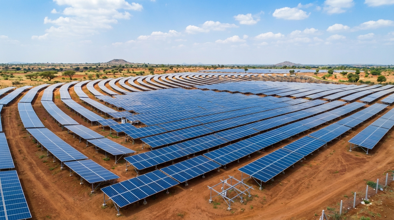
Ground mount solar systems are photovoltaic installations where solar panels are mounted on structures anchored directly to the ground, rather than on building rooftops. These systems are the backbone of India’s utility-scale solar capacity, typically ranging from 1 MW to several hundred megawatts in size. Unlike rooftop installations that must work within existing structural constraints, ground mount India projects offer greater flexibility in system design, orientation, and capacity.
The significance of ground mount systems in India’s solar sector cannot be overstated. As of 2026, ground mount installations account for approximately 75% of India’s total solar capacity, with states like Rajasthan, Gujarat, Karnataka, and Andhra Pradesh hosting some of the world’s largest solar parks. The ability to deploy megawatt-scale projects on available land makes ground mount systems the preferred choice for commercial, industrial, and utility-scale applications.
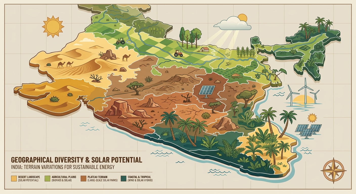
India’s geographical diversity presents both opportunities and challenges for ground mount solar design. The country spans multiple climate zones, soil types, seismic regions, and wind zones—each requiring tailored engineering approaches. A ground mount project in the Thar Desert of Rajasthan faces entirely different design considerations than a coastal installation in Tamil Nadu or a project in the cyclone-prone regions of Odisha.
Current market trends indicate robust growth in the ground mount India sector. The declining cost of solar modules, coupled with improved financing mechanisms and supportive government policies, has made ground mount projects increasingly attractive. However, this growth brings heightened competition and pressure on project margins, making cost-effective and accurate design services more critical than ever for EPC companies seeking to maintain profitability while delivering quality installations.
1. Regional Variations in Ground Mount India Design Requirements
Understanding regional variations is fundamental to successful ground mount India project design. Each geographical zone presents unique characteristics that directly influence engineering decisions, material selection, and construction methodologies. Solar EPCs must account for these regional differences from the earliest feasibility study phase to ensure project viability and optimal performance.
Northern India: Punjab, Haryana, and Rajasthan
The northern states, particularly Rajasthan, represent India’s solar heartland with exceptional solar irradiation levels exceeding 6.5 kWh/m²/day. The Thar Desert region offers vast tracts of barren land ideal for utility-scale ground mount projects. However, desert conditions present specific challenges including extreme temperature variations (from below 0°C in winter to above 50°C in summer), sand movement, and dust accumulation that can reduce panel efficiency by 15-20% without proper mitigation strategies.
Soil conditions in Rajasthan typically consist of sandy and sandy-loam compositions with moderate bearing capacity. Foundation design must account for sand movement and potential erosion, often requiring deeper pile penetration or concrete foundations in areas with poor soil stability. Punjab and Haryana, with their agricultural heritage, present different challenges related to land conversion regulations and the need to navigate agricultural land use policies.
Western India: Gujarat and Maharashtra
Gujarat has emerged as a leader in ground mount solar installations, benefiting from progressive state policies and excellent solar resources. The state’s diverse geography includes coastal areas, industrial zones, and semi-arid regions, each requiring different design approaches. Coastal projects near the Gulf of Khambhat must incorporate corrosion protection measures due to salt spray exposure, typically requiring hot-dip galvanized structures with additional protective coatings.
Maharashtra’s ground mount India projects often utilize industrial land or degraded agricultural areas. The state experiences moderate to high wind speeds during monsoon season, necessitating robust structural engineering to withstand wind loads up to 180 km/h in certain zones. The black cotton soil prevalent in parts of Maharashtra presents foundation challenges due to its expansive nature, requiring specialized foundation design to prevent structural movement during wet-dry cycles.
Southern India: Tamil Nadu, Karnataka, and Andhra Pradesh
Southern states benefit from consistent solar irradiation throughout the year, with Tamil Nadu and Karnataka hosting numerous large-scale solar parks. The tropical climate brings high humidity levels and intense monsoon rainfall, making drainage design a critical component of ground mount projects. Inadequate drainage can lead to waterlogging, foundation erosion, and reduced system performance.
Andhra Pradesh’s coastal regions require special attention to cyclone protection, with structural designs meeting higher wind load requirements as per IS 875 (Part 3). The state’s inland areas feature red soil with good bearing capacity, generally favorable for ground mount installations. Karnataka’s plateau terrain offers relatively stable ground conditions but may require grading and leveling work to optimize panel layout and minimize shading losses.
Eastern India: West Bengal and Odisha
Eastern states present unique challenges for ground mount India projects due to high humidity, heavy monsoon rainfall, and cyclone vulnerability. Odisha, in particular, falls within Cyclone Zone III and IV, requiring structural designs capable of withstanding wind speeds exceeding 200 km/h. This necessitates more robust mounting structures, deeper foundations, and additional bracing—all of which impact project costs.
The alluvial soil common in West Bengal generally provides good bearing capacity, but high groundwater levels can complicate foundation installation and require dewatering during construction. Corrosion protection becomes paramount in these high-humidity environments, with accelerated corrosion rates affecting both above-ground structures and buried components.
Central India: Madhya Pradesh and Chhattisgarh
Central Indian states offer good solar resources and relatively stable ground conditions on the Deccan Plateau. However, many potential project sites involve forest land or areas requiring environmental clearances, adding complexity to the approval process. The feasibility study phase becomes particularly important in these regions to identify and address environmental compliance requirements early in the project timeline.
Madhya Pradesh’s varied topography includes both flat agricultural areas and undulating terrain. Projects on sloped land require careful consideration of grading costs versus the benefits of terrain-following mounting systems. The moderate climate in central India generally presents fewer extreme weather challenges compared to coastal or desert regions, though monsoon drainage remains an important design consideration.
2. Land Requirements and Site Selection for Ground Mount Projects
Accurate land requirement calculations form the foundation of any ground mount India project. The land area needed depends on several factors including system capacity, mounting technology, panel efficiency, and site-specific constraints. As a general guideline, fixed-tilt ground mount systems require approximately 4-5 acres per MW, while single-axis tracking systems need 6-7 acres per MW due to increased row spacing to prevent shading during panel movement.
These figures assume relatively flat terrain with minimal obstacles. Projects on sloped land may require additional area for access roads, drainage channels, and equipment placement. Site topology assessment should identify slopes exceeding 5-10 degrees, as steeper terrain significantly increases grading costs or necessitates terrain-following mounting solutions that add complexity to the structural design.
Beyond raw acreage, site selection must consider proximity to grid infrastructure. Evacuation costs can quickly erode project economics if the nearest substation lies more than 10-15 kilometers away. The feasibility study should evaluate existing transmission capacity, voltage levels, and any grid upgrades required to accommodate the project’s output. Heaven Designs’ site survey and land feasibility services help EPCs identify these critical factors before committing to land acquisition.
Shadow analysis and inter-row spacing optimization directly impact both land utilization and energy yield. Rows spaced too closely will experience shading losses, particularly during early morning and late afternoon hours. Conversely, excessive spacing wastes valuable land and increases balance-of-system costs for cabling and infrastructure. Professional design services use advanced software to model sun paths throughout the year, optimizing row spacing for maximum energy generation while minimizing land requirements.
Environmental clearances represent a significant consideration for ground mount projects, particularly those exceeding 5 MW capacity. Projects on forest land require approval from the Ministry of Environment, Forest and Climate Change, a process that can extend timelines by 12-18 months. Agricultural land conversion involves state-level approvals with varying requirements across different states. Understanding these regulatory pathways during site selection prevents costly delays during project execution.
Soil Conditions and Geotechnical Considerations
Soil conditions fundamentally determine foundation design and represent one of the most critical variables in ground mount India projects. Indian soils vary dramatically by region, from the sandy compositions of Rajasthan to the black cotton soils of Maharashtra and the laterite soils of Kerala. Each soil type exhibits different bearing capacities, drainage characteristics, and behavior under load.
A comprehensive geotechnical investigation should precede detailed engineering design for any ground mount project. This investigation typically includes soil boring at multiple locations across the site, with bore holes extending to depths of 3-6 meters depending on anticipated foundation types. The investigation provides critical data on soil stratification, bearing capacity, groundwater levels, and potential challenges like rock layers or unstable soil conditions.
Key soil testing parameters include Standard Penetration Test (SPT) values, California Bearing Ratio (CBR), and safe bearing capacity. SPT values indicate soil density and strength, with higher values (above 30) suggesting good load-bearing capacity suitable for driven pile foundations. CBR values assess soil strength for pavement and access road design. Safe bearing capacity, typically expressed in kN/m², determines the allowable load that can be safely applied to the soil without risk of excessive settlement or failure.
Soil conditions directly impact foundation selection and costs. Sites with good bearing capacity (above 100 kN/m²) and minimal rock layers are ideal for driven pile foundations, which offer the most cost-effective solution for most ground mount India projects. Poor soil conditions may necessitate concrete foundations or screw piles, increasing foundation costs by 30-50% compared to driven piles. Professional structural engineering services analyze geotechnical data to recommend the most cost-effective foundation solution for specific site conditions.
3. Foundation Types and Structural Engineering for Indian Conditions
Foundation selection represents one of the most consequential decisions in ground mount India project design, directly impacting both capital costs and long-term structural integrity. The foundation must safely transfer loads from the mounting structure and solar panels to the ground while withstanding environmental forces including wind, seismic activity, and soil movement. Indian conditions present diverse foundation challenges requiring tailored engineering solutions.
Driven Pile Foundations
Driven pile foundations are the most common and cost-effective solution for ground mount projects with favorable soil conditions. These foundations consist of steel I-beams or H-beams driven directly into the ground using hydraulic pile drivers. The pile depth typically ranges from 1.5 to 3 meters depending on soil bearing capacity and structural load requirements.
Driven piles work best in sandy, sandy-loam, or clayey soils with SPT values above 15 and minimal rock content. They offer rapid installation, with experienced crews installing 200-300 piles per day. This installation speed translates to shorter construction timelines and reduced labor costs. However, driven piles are unsuitable for rocky terrain where pile driving becomes impractical, or in very soft soils where adequate bearing capacity cannot be achieved.
Regional suitability varies across India. Driven piles perform excellently in the sandy soils of Rajasthan, Gujarat, and Andhra Pradesh. They’re also suitable for the alluvial soils of northern India and the red soils of Karnataka. However, the black cotton soils of Maharashtra and parts of Madhya Pradesh require careful engineering due to their expansive nature, which can cause pile movement during seasonal moisture changes.
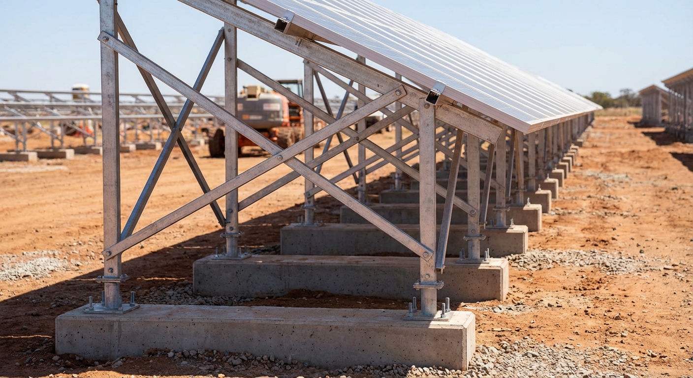
Concrete Foundations
Concrete foundations—both Reinforced Cement Concrete (RCC) and Plain Cement Concrete (PCC)—provide solutions for challenging soil conditions where driven piles are impractical. These foundations typically consist of concrete blocks or footings poured at grade level or in shallow excavations. The concrete mass and base area distribute loads over a larger soil surface, making them suitable for lower bearing capacity soils.
RCC foundations incorporate steel reinforcement for additional strength and are specified for projects in high wind zones or seismic areas where structural loads exceed the capacity of plain concrete. PCC foundations without reinforcement offer a more economical option for sites with moderate loading conditions. Both types require curing time of 14-28 days before mounting structure installation can proceed, extending construction timelines compared to driven piles.
Concrete foundations are particularly relevant for ground mount India projects in rocky terrain where pile driving is impossible, or in areas with very soft soils requiring larger bearing surfaces. The trade-off involves higher material costs and longer installation times, typically increasing foundation costs by 40-60% compared to driven piles. However, they provide superior stability in challenging conditions and may be the only viable option for certain sites.
Screw Pile Foundations
Screw pile foundations represent an emerging technology in the Indian ground mount market, offering advantages in specific applications. These foundations feature helical blades welded to a central shaft, which are screwed into the ground using hydraulic torque motors. The helical blades provide bearing capacity through both end bearing and shaft friction.
Screw piles excel in sites with variable soil conditions or where minimal ground disturbance is required. Installation generates no spoil or excavated material, making them attractive for environmentally sensitive sites. They can be installed in most soil types except solid rock, and installation speed approaches that of driven piles once equipment and crews are mobilized.
The primary limitation of screw piles in India remains cost. Screw pile systems typically cost 20-30% more than driven piles due to higher material costs and specialized installation equipment. However, for projects where soil conditions make driven piles marginal or where rapid installation is critical, screw piles offer a viable alternative. Their use is growing in southern and western India where soil variability makes them increasingly attractive.
Ballasted Systems
Ballasted foundations use concrete blocks or other heavy materials placed on the ground surface to anchor mounting structures through weight alone, without ground penetration. While common in rooftop solar installations, ballasted systems see limited application in ground mount India projects due to higher material costs and land use inefficiency.
Ballasted systems may be considered for sites where ground penetration is prohibited due to environmental restrictions, underground utilities, or contaminated soil. They’re also relevant for temporary installations or demonstration projects. However, the large quantity of ballast required—typically 50-80 kg per square meter of panel area—makes them economically impractical for utility-scale projects. Wind load requirements in Indian conditions further increase ballast requirements, compounding cost challenges.
Seismic Design Considerations
India’s seismic zonation, defined by IS 1893, divides the country into four seismic zones (II through V) with varying earthquake risk levels. Ground mount India projects must incorporate seismic design provisions appropriate to their location. Zone V areas, including parts of Jammu & Kashmir, Himachal Pradesh, and the northeastern states, require the most stringent seismic design with higher safety factors and additional structural bracing.
Most major solar development regions fall within Zone II (low seismic risk) or Zone III (moderate seismic risk), including Rajasthan, Gujarat, Karnataka, and Andhra Pradesh. Even in these moderate zones, proper seismic design ensures structural integrity during earthquake events. This includes foundation design to prevent uplift or sliding, structural connections capable of accommodating seismic forces, and mounting structure flexibility to absorb ground motion without failure.
Professional structural engineering services incorporate seismic analysis into ground mount designs, calculating lateral forces and ensuring adequate structural capacity. The incremental cost of seismic design provisions is minimal—typically 2-5% of structural costs—while providing essential protection for the 25-year project lifespan. Heaven Designs’ engineering team ensures all ground mount India projects meet applicable seismic code requirements based on project location.
4. Terrain Challenges and Site-Specific Design Solutions
Terrain characteristics significantly influence ground mount India project design, construction complexity, and overall costs. While flat, unobstructed sites represent the ideal scenario, many projects must contend with challenging terrain conditions that require specialized engineering solutions. Understanding how to address these challenges cost-effectively separates successful EPCs from those who struggle with project margins.
Flat Terrain Optimization
Flat terrain offers the greatest flexibility for ground mount design and typically results in the lowest construction costs. On sites with slopes less than 2-3 degrees, minimal grading is required, and standard mounting structures can be deployed efficiently. The primary design focus shifts to maximizing land utilization while maintaining optimal inter-row spacing to prevent shading losses.
Even on flat sites, micro-topography matters. Subtle elevation changes can create drainage issues if not properly addressed. The design should incorporate gentle grading to direct water away from equipment areas and prevent pooling around foundations. Access roads should be positioned to minimize panel shading while providing efficient access for construction equipment and ongoing maintenance activities.
Sloped Terrain Considerations
Sites with slopes between 5-15 degrees present design choices that significantly impact project economics. The first option involves extensive grading to create level terraces for standard mounting structures. This approach simplifies structural design but incurs substantial earthwork costs—often ₹50,000 to ₹150,000 per acre depending on slope severity and soil conditions. Grading also creates environmental concerns related to erosion and vegetation removal.
The alternative approach uses terrain-following mounting structures that adapt to existing ground contours. These systems minimize earthwork but require custom structural design and more complex foundation layouts. For east-west oriented slopes, terrain-following designs can actually improve energy yield by optimizing panel orientation. North-south slopes present greater challenges, potentially requiring a mix of grading and adaptive structures to maintain acceptable panel angles.
The economic break-even between grading and terrain-following systems typically occurs around 8-10 degree slopes, though this varies based on local earthwork costs and soil conditions. Professional design services perform detailed cost-benefit analysis to recommend the optimal approach for specific sites, considering both capital costs and long-term energy production impacts.
Rocky Terrain Solutions
Rocky terrain presents significant foundation challenges for ground mount India projects. Sites with rock layers within 2-3 meters of the surface make driven pile installation difficult or impossible. Pre-drilling or rock excavation becomes necessary, dramatically increasing foundation installation time and costs. In extreme cases, foundation costs can double or triple compared to favorable soil conditions.
Design solutions for rocky terrain include concrete foundations poured into excavated pockets, screw piles with rock-cutting capabilities, or hybrid approaches using different foundation types in different site areas. The geotechnical investigation becomes particularly critical for rocky sites, as rock depth and hardness vary significantly even within a single project area. Identifying rock conditions early allows accurate cost estimation and appropriate foundation selection.
Some rocky terrain sites, particularly in hilly regions, may prove economically unviable for ground mount development due to excessive foundation and grading costs. The feasibility study should include preliminary geotechnical assessment to identify potential deal-breakers before significant resources are committed to project development.
Waterlogged and Marshy Areas
Waterlogged sites and marshy areas require specialized drainage solutions and foundation designs to ensure long-term stability. High groundwater levels can cause foundation settlement, corrosion acceleration, and electrical safety concerns. These sites are generally avoided for ground mount projects unless no alternatives exist, as mitigation costs often prove prohibitive.
When waterlogged sites must be developed, solutions include perimeter drainage systems to lower groundwater levels, raised foundations to elevate structures above seasonal water levels, and enhanced corrosion protection for all buried components. Dewatering during construction adds complexity and cost. The electrical design must incorporate additional safety measures including enhanced grounding systems and protection against ground faults in wet conditions.
Desert Conditions
Desert environments in Rajasthan and Gujarat offer excellent solar resources but present unique engineering challenges. Extreme temperature variations cause significant thermal expansion and contraction in mounting structures, requiring expansion joints and flexible connections to prevent structural stress. Daily temperature swings of 30-40°C are common, with summer ground temperatures exceeding 60°C.
Sand movement poses risks to foundations and electrical equipment. Wind-driven sand can accumulate around foundation bases, creating uneven loading and potential structural issues. Design solutions include foundation depths extending below the active sand layer (typically 1.5-2 meters), protective barriers around equipment enclosures, and regular maintenance protocols for sand removal.
Dust accumulation significantly impacts panel performance in desert regions, with soiling losses reaching 15-20% without regular cleaning. While not strictly a structural design issue, the design should facilitate cleaning operations through adequate row spacing for cleaning equipment access and water supply infrastructure planning. Some projects incorporate automated cleaning systems, requiring additional structural support and utility connections.
Coastal Area Considerations
Coastal ground mount India projects face accelerated corrosion from salt spray exposure, particularly within 5-10 kilometers of the shoreline. Standard hot-dip galvanized steel structures may experience premature corrosion in these environments, potentially compromising structural integrity within 10-15 years instead of the expected 25-year lifespan.
Corrosion protection strategies for coastal projects include thicker galvanization (minimum 120 microns instead of standard 80 microns), additional protective coatings such as zinc-rich primers or epoxy coatings, and use of marine-grade stainless steel for critical fasteners and connections. These measures increase material costs by 15-25% but are essential for long-term durability.
Coastal areas also experience higher wind loads and potential cyclone exposure. Structural designs must meet enhanced wind load requirements, often necessitating more robust mounting structures, additional bracing, and deeper foundations. The combination of corrosion protection and enhanced structural requirements makes coastal ground mount projects more expensive than inland installations, though excellent solar resources and proximity to demand centers often justify the additional investment.
5. Climate Considerations for Ground Mount India Projects
India’s diverse climate zones—from tropical to arid to temperate, create varying environmental stresses on ground mount solar installations. Climate-responsive design ensures structural durability, optimal performance, and minimal maintenance requirements throughout the project’s 25-year operational life. Understanding regional climate patterns and incorporating appropriate design provisions separates robust installations from those plagued by premature failures and performance issues.
Monsoon Impact and Drainage Design
The Indian monsoon delivers 70-80% of annual rainfall in a concentrated 3-4 month period, creating intense drainage challenges for ground mount projects. Inadequate drainage design leads to waterlogging, foundation erosion, soil settlement, and potential structural damage. Sites in high-rainfall regions like Kerala, coastal Karnataka, and northeastern states may receive 2000-3000 mm of annual rainfall, with individual storm events delivering 100-200 mm in 24 hours.
Effective drainage design begins with site grading to establish positive drainage away from equipment areas and toward designated drainage channels. The design should prevent water accumulation around inverter pads, transformer foundations, and electrical equipment. Drainage channels must be sized to handle peak rainfall events, typically designed for 1-in-25-year or 1-in-50-year storm intensities depending on project risk tolerance.
Foundation design must account for potential soil erosion during heavy rainfall. Driven piles should extend below the erosion-prone surface layer, typically a minimum of 1.5 meters depth. Concrete foundations may require erosion protection measures including riprap or vegetation around the foundation perimeter. Access roads need proper drainage culverts to prevent washouts that could isolate sections of the project during monsoon season.
Wind Load Calculations
Wind loads represent the dominant structural design force for most ground mount India projects. IS 875 (Part 3) divides India into six wind zones with basic wind speeds ranging from 33 m/s to 55 m/s (approximately 120-200 km/h). Coastal areas and cyclone-prone regions experience the highest wind loads, while inland areas generally face moderate wind conditions.
Structural design must consider both sustained wind loads and peak gust forces. Solar panels present large surface areas that act as sails, creating significant uplift and overturning forces on mounting structures. The design must ensure adequate foundation capacity to resist these forces with appropriate safety factors, typically 1.5 to 2.0 depending on project location and risk assessment.
Wind tunnel testing or computational fluid dynamics (CFD) analysis may be warranted for large projects or those in high wind zones. These analyses identify localized wind acceleration effects and help optimize structural design. For most projects, code-based wind load calculations following IS 875 provide adequate design basis when properly applied by experienced structural engineers.
Temperature Variations and Thermal Expansion
India’s temperature extremes, from below freezing in northern winters to above 50°C in desert summers, create significant thermal expansion and contraction in mounting structures. Aluminum and steel components expand approximately 12-23 microns per meter per degree Celsius. For a 50-meter row of panels experiencing a 40°C temperature swing, this translates to 24-46 mm of expansion that must be accommodated in the structural design.
Mounting structures require expansion joints or flexible connections to prevent thermal stress accumulation. Fixed connections at every foundation point create internal stresses that can lead to structural fatigue or connection failures. The design typically incorporates fixed anchor points at regular intervals with sliding connections between, allowing thermal movement without stress buildup.
Electrical components also face thermal challenges. Inverters and transformers must be rated for ambient temperatures up to 50°C in desert regions, or derated to prevent overheating and premature failure. Cable sizing must account for temperature derating factors, with larger conductors required in high-temperature environments to maintain acceptable current-carrying capacity and minimize resistive losses.
Dust and Soiling Management
Dust accumulation reduces panel efficiency by blocking sunlight, with soiling losses varying dramatically across Indian regions. Desert areas of Rajasthan experience the highest soiling rates, with efficiency losses reaching 15-20% within 2-3 weeks without cleaning. Coastal areas face salt deposition in addition to dust. Agricultural regions experience seasonal dust from harvesting activities and crop residue burning.
While cleaning protocols address soiling operationally, design decisions influence cleaning effectiveness and costs. Adequate row spacing allows access for cleaning equipment, whether manual labor with water and brushes or mechanized cleaning systems. Water supply infrastructure should be planned during the design phase, including storage tanks, distribution piping, and water source identification.
Panel tilt angle influences soiling accumulation, with steeper tilts (above 20 degrees) experiencing some self-cleaning during rainfall. However, tilt angle optimization must balance soiling considerations against energy yield maximization. For most Indian locations, tilts between 15-25 degrees provide the best compromise between annual energy production and soiling management.
Hailstorm Protection
Hailstorms occur primarily in northern India during pre-monsoon months (March-May), with states like Punjab, Haryana, and Uttar Pradesh experiencing the highest frequency. While modern solar panels are tested to withstand 25mm hailstones at 23 m/s (IEC 61215 standard), larger hailstones can cause panel damage resulting in costly replacements and production losses.
Design mitigation for hail risk is limited, as panels must face upward to capture sunlight. The primary protection comes from specifying panels with tempered glass meeting appropriate impact resistance standards. Some projects in high-risk areas incorporate hail detection systems that can tilt tracking systems to vertical positions during hailstorms, minimizing impact angles. However, this option applies only to tracking systems and adds system complexity and cost.
Insurance coverage typically addresses hail damage risk, though premiums reflect regional risk levels. The design documentation should clearly specify panel impact resistance ratings to support insurance underwriting and claims processes. Proper installation following manufacturer specifications ensures panels meet their rated impact resistance without compromised performance.
Humidity and Corrosion Protection
High humidity regions, including coastal areas and eastern states, experience accelerated corrosion rates affecting both structural components and electrical equipment. Relative humidity levels consistently above 70-80% create conditions favorable for corrosion, particularly when combined with salt exposure in coastal areas or industrial pollutants in urban-adjacent sites.
Corrosion protection begins with material selection. Hot-dip galvanization provides the primary protection for steel structures, with coating thickness specified based on environmental conditions. Standard galvanization of 80 microns suffices for inland areas with moderate humidity, while coastal and high-humidity regions require 120 microns or greater. Aluminum structures offer inherent corrosion resistance but at higher material costs.
Electrical equipment requires environmental ratings appropriate to site conditions. Inverters and combiner boxes should have IP65 or higher ingress protection ratings in high-humidity areas. Cable glands, connectors, and junction boxes must be properly sealed to prevent moisture ingress. Regular inspection and maintenance protocols should include corrosion monitoring, with touch-up coating applied to any areas showing corrosion initiation.
Module Mounting Structures and Tracking Systems
The choice between fixed-tilt and tracking systems significantly impacts both project costs and energy yield. Fixed-tilt systems mount panels at a static angle optimized for the site’s latitude, typically ranging from 10-25 degrees across different Indian locations. These systems offer the lowest capital cost, minimal maintenance requirements, and proven long-term reliability.
Single-axis tracking systems rotate panels to follow the sun’s east-west movement throughout the day, increasing energy yield by 15-25% compared to fixed-tilt systems. However, tracking systems cost approximately 20-30% more than fixed-tilt installations and require larger land areas due to increased row spacing. The return on investment for tracking systems depends on electricity tariffs, land costs, and site-specific solar resources.
For most ground mount India projects in 2026, single-axis tracking has become economically attractive for utility-scale installations above 10-20 MW capacity. The additional energy yield justifies the higher capital cost, particularly in high-irradiation regions like Rajasthan and Gujarat. Smaller commercial projects (1-5 MW) typically favor fixed-tilt systems due to lower complexity and better economics at smaller scales.
Seasonal tilt adjustment systems offer a middle ground, using manual or motorized mechanisms to adjust panel tilt 2-4 times annually to optimize for seasonal sun angles. These systems capture 5-8% additional energy compared to fixed-tilt while costing significantly less than single-axis tracking. They’re particularly relevant for projects where land constraints make tracking systems impractical but owners seek performance improvements beyond fixed-tilt systems.
Material selection for mounting structures involves trade-offs between cost, durability, and structural performance. Galvanized steel remains the dominant choice for Indian ground mount projects, offering excellent strength-to-cost ratios and proven durability with proper corrosion protection. Aluminum structures provide superior corrosion resistance and lighter weight but cost 30-40% more than steel. The choice depends on site-specific corrosion risk, structural load requirements, and project budget constraints.
6. Regulatory Requirements and Compliance for Ground Mount Solar
Navigating India’s regulatory landscape represents a critical success factor for ground mount projects. The regulatory framework spans central government standards, state-level policies, environmental regulations, and local authority approvals. Understanding these requirements and incorporating compliance into project timelines prevents costly delays and ensures smooth project execution from design through commissioning.
Central Electricity Authority (CEA) Regulations
The Central Electricity Authority establishes technical standards for grid-connected solar installations through various regulations and technical specifications. The CEA (Technical Standards for Connectivity of the Distributed Generation Resources) Regulations, 2013, and subsequent amendments define requirements for grid interconnection, safety systems, and technical performance standards.
Key CEA requirements affecting ground mount India design include specifications for inverter characteristics, power quality parameters, protection systems, and metering arrangements. Designs must ensure compliance with voltage and frequency operating ranges, harmonic distortion limits, and reactive power capability requirements. The electrical design documentation must demonstrate compliance with these standards to obtain grid connectivity approvals.
CEA regulations also mandate safety systems including anti-islanding protection, which prevents the solar system from energizing the grid during utility outages. Ground fault detection and arc fault protection requirements ensure electrical safety during operation. Professional electrical design services ensure all protection systems are properly specified and coordinated with utility requirements.
State-Level Policies and Incentives
Individual states maintain their own solar policies, incentive programs, and approval processes that significantly impact project development. Progressive states like Gujarat, Rajasthan, and Karnataka have streamlined approval processes and offer various incentives including capital subsidies, accelerated depreciation benefits, and preferential tariffs for solar power.
State policies govern critical aspects including land use permissions, agricultural land conversion procedures, and local authority approvals. Some states restrict solar development on prime agricultural land, while others have established clear conversion processes with defined timelines and fees. Understanding state-specific requirements during the feasibility phase prevents surprises during project execution.
Net metering and banking regulations vary by state, affecting project economics for commercial and industrial installations. Some states offer favorable banking provisions allowing annual energy accounting, while others impose monthly banking limits or banking charges. The project’s financial model must reflect applicable state policies to ensure accurate return on investment projections.
Environmental Impact Assessment (EIA)
Environmental clearance requirements depend on project size and location. Solar projects exceeding 20 MW capacity in ecologically sensitive areas require Environmental Impact Assessment under the Environmental Impact Assessment Notification, 2006. Projects on forest land require separate forest clearance regardless of capacity, a process that can extend timelines by 12-18 months.
The EIA process involves baseline environmental data collection, impact assessment, public consultation, and mitigation planning. While most ground mount projects have minimal environmental impact compared to other industrial activities, the formal EIA process must be completed before construction can commence. Early engagement with environmental consultants and regulatory authorities helps manage this timeline effectively.
Even projects not requiring formal EIA should conduct environmental due diligence to identify potential issues including protected species habitat, wetlands, archaeological sites, or other sensitive features. Addressing these issues proactively prevents project delays and demonstrates responsible development practices to stakeholders and financing institutions.
Land Conversion and NOC Requirements
Land use conversion represents one of the most complex regulatory aspects of ground mount India projects. Agricultural land conversion to industrial or commercial use requires state government approval, with processes varying significantly across states. Some states have established single-window clearance systems, while others involve multiple departments and extended approval timelines.
No Objection Certificates (NOCs) may be required from various authorities including local panchayats, pollution control boards, fire departments, and airport authorities if projects are located near airports. The specific NOC requirements depend on project location and local regulations. Comprehensive regulatory mapping during the feasibility phase identifies all required approvals and establishes realistic timeline expectations.
Land title verification and encumbrance checks are essential before land acquisition. Clear title free from disputes, mortgages, or other encumbrances is critical for project financing and development. Legal due diligence should be completed early in the project development process to avoid costly discoveries after land purchase commitments are made.
Grid Connectivity and Evacuation Approvals
Grid connectivity approval from the relevant distribution or transmission utility is mandatory before project commissioning. The application process involves technical documentation including single-line diagrams, protection schemes, and equipment specifications. Utilities review applications to ensure grid stability and adequate evacuation capacity.
Evacuation infrastructure requirements depend on project size and grid proximity. Small projects (under 5 MW) typically connect at distribution voltage levels (11-33 kV), while larger projects require transmission-level connections (66-220 kV). Transmission connections involve more complex approval processes and may require dedicated substations or transmission line construction, adding significant costs and timeline.
Some regions face grid congestion limiting new solar project connections. Identifying evacuation constraints during feasibility assessment prevents investing in projects that cannot obtain timely grid connectivity. Coordination with utilities early in project development helps secure connectivity agreements and identify any required grid upgrades or cost-sharing arrangements.
Building Codes and Structural Certifications
While ground mount solar installations are not buildings in the traditional sense, structural designs must comply with relevant Indian Standards including IS 875 (Design Loads for Buildings and Structures), IS 800 (Code of Practice for General Construction in Steel), and IS 1893 (Criteria for Earthquake Resistant Design of Structures). Compliance with these standards ensures structural safety and is typically required for project financing and insurance.
Structural design calculations and drawings should be certified by licensed structural engineers. This certification provides assurance to project owners, lenders, and insurers that designs meet applicable safety standards and will perform as intended throughout the project lifespan. Heaven Designs’ structural engineering services include comprehensive calculations and certifications meeting all applicable Indian Standards.
Permit Design Documentation and Approval Timelines
The permit design package encompasses all documentation required for regulatory approvals, including site plans, structural drawings, electrical single-line diagrams, equipment specifications, and compliance certifications. Complete and accurate documentation accelerates approval processes, while incomplete or non-compliant submissions result in rejection and resubmission delays.
Approval timelines vary significantly based on project location, size, and complexity. Simple projects on industrial land with existing grid connectivity may obtain all approvals within 2-3 months. Complex projects involving agricultural land conversion, environmental clearances, or new transmission connections may require 12-18 months for complete regulatory approval. The project timeline must account for these regulatory processes to establish realistic commissioning dates.
Professional permit design services ensure documentation meets all regulatory requirements, reducing approval timelines and preventing costly resubmissions. Experienced design partners understand state-specific requirements and maintain relationships with regulatory authorities, facilitating smoother approval processes for EPC clients.
7. Design Process and Engineering Documentation for EPCs
A structured design process ensures ground mount India projects are optimized for performance, cost, and regulatory compliance. The design process typically progresses through distinct phases, each building on previous work and adding detail as the project advances from concept to construction-ready documentation. Understanding this process helps EPCs manage timelines, budgets, and stakeholder expectations effectively.
Site Survey and Feasibility Study Phase
Every successful ground mount project begins with comprehensive site assessment and feasibility analysis. The site survey collects critical data including topographic mapping, soil conditions, solar resource assessment, grid connectivity evaluation, and regulatory constraint identification. This information forms the foundation for all subsequent design decisions and project viability assessment.
Topographic surveys using GPS or drone-based photogrammetry create detailed site maps showing elevation contours, existing structures, vegetation, and access routes. Survey accuracy directly impacts design quality, with utility-scale projects typically requiring surveys accurate to within 10-20 cm vertically. The topographic data feeds into layout optimization software to minimize grading costs and maximize energy yield.
Geotechnical investigation identifies soil conditions and bearing capacity across the site. For large projects, multiple bore holes at 50-100 meter spacing provide comprehensive soil data. The geotechnical report includes soil stratification, SPT values, bearing capacity recommendations, and foundation design parameters. This information is critical for accurate foundation cost estimation and structural design.
Solar resource assessment uses satellite data or on-site measurement to quantify available solar irradiation. While satellite data provides adequate accuracy for most projects, large utility-scale developments may justify on-site measurement stations collecting 12+ months of data. The solar resource assessment feeds into energy yield modeling and project financial analysis.
The feasibility study synthesizes all site data to assess project viability. This analysis evaluates technical feasibility, regulatory requirements, grid connectivity options, preliminary cost estimates, and financial returns. A thorough feasibility study identifies potential deal-breakers early, preventing wasted investment in non-viable projects. Heaven Designs’ site survey and feasibility services provide EPCs with the critical information needed for informed project decisions.
Preliminary Design and Layout Optimization
The preliminary design phase translates feasibility study findings into initial project layouts and system configurations. This phase explores design alternatives, optimizes system sizing, and establishes the basic project architecture that will guide detailed engineering. Key decisions made during preliminary design include mounting system selection (fixed-tilt vs. tracking), module and inverter selection, electrical architecture, and overall site layout.
Layout optimization balances multiple objectives including maximum energy yield, minimum land use, optimal equipment utilization, and construction efficiency. Advanced design software models sun paths throughout the year, calculating shading losses for different row spacings and orientations. The optimization process identifies the layout configuration that maximizes project returns while meeting site constraints.
Equipment selection during preliminary design considers performance, cost, availability, and compatibility. Module selection balances efficiency, cost per watt, and manufacturer reputation. Inverter selection involves sizing decisions (string vs. central inverters), voltage level selection, and manufacturer evaluation. These equipment decisions significantly impact both capital costs and long-term performance.
The preliminary design deliverable typically includes site layout drawings, single-line electrical diagrams, equipment specifications, preliminary bill of quantities, and updated cost estimates. This documentation supports project financing applications, EPC bidding processes, and internal project approval decisions. The preliminary design provides sufficient detail for accurate cost estimation while remaining flexible for optimization during detailed engineering.
Detailed Engineering Design Deliverables
Detailed engineering design produces construction-ready documentation covering all project aspects. This comprehensive design package enables accurate procurement, efficient construction, and regulatory compliance. The detailed design phase typically requires 4-8 weeks for projects in the 1-10 MW range, with larger projects requiring proportionally longer design periods.
Civil engineering deliverables include grading plans, drainage designs, access road layouts, foundation drawings, and earthwork quantities. Foundation drawings specify pile types, depths, spacing, and installation requirements for each mounting structure location. Drainage designs show channel locations, sizing, and erosion protection measures. These drawings guide civil construction contractors and enable accurate cost estimation.
Structural engineering documentation includes mounting structure designs, connection details, material specifications, and structural calculations. The structural drawings show assembly details for mounting structures, panel attachment methods, and all structural connections. Structural calculations demonstrate compliance with wind load, seismic, and dead load requirements per applicable Indian Standards. Professional engineers certify these calculations, providing assurance of structural adequacy.
Electrical engineering deliverables encompass DC system design, AC system design, protection schemes, grounding design, and equipment specifications. DC design drawings show string configurations, combiner box locations, and DC cabling routes. AC design includes inverter locations, transformer sizing, AC collection system design, and grid interconnection details. Protection system design ensures safe operation and grid code compliance.
The bill of quantities (BOQ) provides detailed material quantities for all project components, enabling accurate procurement and cost control. The BOQ breaks down quantities by category (civil, structural, electrical, etc.) and includes specifications for each item. Accurate BOQ preparation prevents material shortages or excess procurement that ties up working capital.
Structural Engineering Calculations and Certifications
Structural engineering represents a critical component of ground mount India design, ensuring installations withstand environmental loads throughout their 25-year lifespan. Structural calculations analyze all load cases including dead loads (panel and structure weight), wind loads, seismic loads, and combined load scenarios. The analysis determines required structural member sizes, connection capacities, and foundation requirements.
Wind load analysis typically governs structural design for most Indian locations. The analysis applies wind pressure to panel surfaces based on IS 875 (Part 3), calculating uplift forces, overturning moments, and lateral loads. The structural design must resist these forces with adequate safety factors, typically 1.5 for strength and 2.0 for stability against overturning.
Foundation design calculations determine required pile depths, concrete dimensions, or other foundation parameters based on soil bearing capacity and applied loads. The calculations ensure foundations resist uplift, overturning, and sliding with appropriate safety factors. Foundation design must also consider long-term settlement and soil behavior under cyclic loading.
Professional engineer certification of structural calculations provides assurance to project stakeholders that designs meet applicable standards and safety requirements. This certification is typically required for project financing, insurance underwriting, and regulatory approvals. Heaven Designs’ team of licensed structural engineers provides comprehensive calculations and certifications for all ground mount projects.
Electrical Design: DC and AC System Sizing
Electrical design optimization significantly impacts both project costs and energy production. DC system design determines string configurations, combiner box locations, and DC cabling architecture. String sizing must account for module voltage-temperature characteristics, inverter input voltage ranges, and voltage drop limitations. Proper string design maximizes inverter utilization while ensuring safe operation across all temperature conditions.
Inverter sizing involves the DC-to-AC ratio decision, balancing capital cost against energy yield. Modern ground mount projects typically use DC-to-AC ratios between 1.2 and 1.4, accepting some inverter clipping during peak production hours in exchange for better inverter utilization during morning, evening, and cloudy conditions. The optimal ratio depends on site solar resources, electricity pricing structures, and equipment costs.
AC system design includes transformer sizing, AC collection system architecture, and grid interconnection design. The AC collection system must minimize electrical losses while maintaining reasonable cable costs. Voltage level selection (typically 11 kV, 33 kV, or higher for large projects) impacts cable sizing, transformer requirements, and overall system costs. Professional electrical design services optimize these trade-offs for minimum lifecycle costs.
Civil Works Drawings and BOQ Preparation
Civil works documentation guides site preparation, foundation installation, and infrastructure construction. Grading plans show cut and fill requirements to achieve desired site contours, with earthwork quantities calculated for cost estimation and contractor bidding. Drainage plans detail channel locations, sizing, and erosion control measures to protect the installation from water damage.
Access road layouts ensure construction equipment access and ongoing maintenance vehicle circulation. Road designs must accommodate heavy equipment during construction while minimizing long-term maintenance requirements. Road specifications include base preparation, surface materials, and drainage provisions to prevent deterioration during monsoon seasons.
Foundation installation drawings provide detailed specifications for each foundation type used in the project. For driven pile foundations, drawings specify pile profiles, depths, and installation tolerances. Concrete foundation drawings show dimensions, reinforcement details, and concrete specifications. These drawings enable accurate contractor bidding and ensure consistent installation quality.
PMC Services for Project Execution Oversight
Project Management Consultancy (PMC) services extend design expertise into the construction phase, ensuring designs are implemented correctly and project objectives are achieved. PMC services include construction supervision, quality assurance, progress monitoring, and commissioning support. For EPCs managing multiple projects or entering new markets, PMC services provide valuable expertise and risk mitigation.
Construction supervision ensures work proceeds according to approved designs and specifications. PMC engineers conduct regular site inspections, review contractor submittals, and verify material quality. This oversight prevents construction errors that could compromise performance or safety. Early identification of issues enables corrective action before problems become costly to remedy.
Quality assurance activities include foundation installation verification, structural assembly inspection, electrical testing, and commissioning support. PMC services ensure all systems meet design specifications and performance requirements before project handover. This independent verification provides assurance to project owners and financing institutions that installations will perform as projected.
Heaven Designs’ PMC services leverage the same engineering expertise used in design to support successful project execution. This continuity from design through construction ensures design intent is maintained and provides EPCs with a single point of accountability for project technical performance.
Design Software and Tools for Ground Mount India Projects
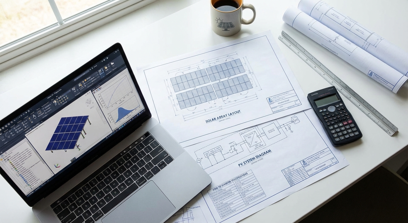
Modern design software enables rapid iteration, optimization, and accurate analysis of ground mount solar projects. Leading software platforms including PVsyst, Helioscope, and AutoCAD form the foundation of professional solar design workflows. These tools enable designers to model complex scenarios, optimize layouts, and generate accurate energy yield predictions.
PVsyst provides comprehensive energy modeling capabilities, simulating system performance hour-by-hour throughout the year. The software accounts for temperature effects, shading losses, soiling, and all other factors affecting energy production. PVsyst reports form the basis for project financial modeling and are typically required by financing institutions for project approval.
Layout optimization software automates the process of positioning panels, calculating shading losses, and optimizing row spacing. These tools can evaluate thousands of layout variations in minutes, identifying configurations that maximize energy yield while meeting site constraints. The optimization process significantly improves project economics compared to manual layout approaches.
Structural analysis software enables detailed modeling of mounting structures and foundations, verifying designs meet load requirements with adequate safety margins. Finite element analysis tools model complex load distributions and identify potential stress concentrations. These analysis capabilities ensure structural designs are both safe and cost-optimized.
Cost Optimization Strategies for Ground Mount Projects
Cost optimization begins during design, where decisions made on paper significantly impact construction costs and long-term performance. The most effective cost optimization strategies balance initial capital costs against long-term energy production and maintenance requirements, focusing on lifecycle value rather than simply minimizing upfront costs.
Foundation optimization represents one of the highest-impact cost reduction opportunities. Selecting the most appropriate foundation type for site conditions prevents over-engineering while ensuring adequate structural capacity. Detailed geotechnical investigation enables confident foundation selection, avoiding conservative assumptions that inflate costs unnecessarily. For a 10 MW project, optimized foundation design can save ₹50-100 lakhs compared to overly conservative approaches.
Module layout optimization maximizes energy yield from available land while minimizing balance-of-system costs. Optimal row spacing reduces shading losses without excessive land use or cabling costs. The optimization process considers site-specific solar resources, land costs, and equipment prices to identify the configuration delivering maximum project returns. Professional design services using advanced optimization software consistently achieve 2-5% better project economics compared to manual layout approaches.
Electrical system optimization reduces losses and equipment costs through intelligent inverter sizing, optimal DC-to-AC ratios, and efficient AC collection system design. Oversized inverters waste capital, while undersized inverters sacrifice energy production. The optimal balance depends on site solar resources and equipment costs, requiring detailed analysis to identify the best configuration for specific projects.
Value engineering reviews identify opportunities to reduce costs without compromising quality or performance. This process examines all design elements, questioning whether simpler or less expensive alternatives could achieve project objectives. Value engineering might identify opportunities to use standard components instead of custom designs, optimize material specifications, or simplify construction sequences to reduce labor costs.
Professional design services deliver cost optimization through experience, specialized software tools, and systematic analysis. The design fee, typically 1-3% of project costs, generates returns many times greater through optimized designs that reduce construction costs, maximize energy yield, and minimize long-term maintenance requirements. Heaven Designs’ engineering team has delivered over 628 MW of optimized designs, consistently helping EPC clients improve project economics while maintaining quality and performance standards.
8. Common Challenges and Solutions for Ground Mount India Projects
Despite careful planning, ground mount projects frequently encounter challenges during development and construction. Understanding common issues and proven solutions helps EPCs anticipate problems, implement preventive measures, and respond effectively when issues arise. The following challenges represent the most frequent obstacles faced by ground mount India projects in 2026.
Land Acquisition Delays and Mitigation Strategies
Land acquisition often represents the longest and most unpredictable phase of project development. Challenges include unclear land titles, multiple owners requiring coordination, agricultural land conversion approvals, and local opposition to land use changes. These issues can delay projects by 6-18 months, jeopardizing financing commitments and power purchase agreements.
Mitigation strategies begin with thorough legal due diligence before land purchase commitments. Title verification, encumbrance checks, and ownership confirmation prevent costly discoveries after agreements are signed. Engaging local facilitators who understand community dynamics and can address concerns proactively reduces opposition and smooths approval processes.
Alternative land acquisition approaches including long-term leases rather than purchases can accelerate project development while reducing capital requirements. Lease agreements with clear terms, escalation provisions, and exit clauses provide flexibility while securing land access. Some EPCs partner with land aggregators who specialize in assembling suitable parcels, transferring land acquisition risk and timeline uncertainty to specialized partners.
Dealing with Poor Soil Conditions Cost-Effectively
Unexpected soil conditions discovered during construction represent a common source of cost overruns and delays. Poor bearing capacity, rock layers, or high groundwater levels can necessitate foundation design changes and additional costs. These surprises typically result from inadequate geotechnical investigation during the design phase.
The solution lies in comprehensive geotechnical investigation before detailed design and cost estimation. While geotechnical studies add upfront costs (typically ₹50,000-200,000 depending on project size), they prevent much larger cost overruns during construction. The investigation should include sufficient bore holes to characterize soil variability across the site, with additional investigation in areas showing concerning conditions.
When poor soil conditions are identified, professional structural engineering services can develop cost-effective solutions. Options might include alternative foundation types, localized soil improvement, or layout modifications to avoid problematic areas. Early identification enables these solutions to be incorporated into the design rather than implemented as expensive change orders during construction.
Managing Seasonal Construction Challenges
India’s monsoon season creates construction challenges for ground mount projects, particularly for civil works and foundation installation. Heavy rainfall makes sites inaccessible, prevents concrete curing, and delays pile driving in saturated soils. Projects that fail to account for seasonal constraints in scheduling face extended timelines and potential cost increases.
Effective project scheduling aligns construction activities with favorable weather windows. Civil works and foundation installation should be scheduled for dry seasons, with electrical and commissioning work planned for periods when weather is less critical. For projects spanning multiple seasons, phased construction approaches can maintain progress while avoiding weather-sensitive activities during unfavorable periods.
Design decisions can also mitigate seasonal challenges. Adequate drainage design prevents site flooding and enables faster site recovery after rainfall. Foundation types that can be installed in varied conditions (such as screw piles) provide more scheduling flexibility than methods requiring dry conditions. These design considerations should be evaluated during the planning phase based on anticipated construction schedules.
Grid Connectivity and Evacuation Bottlenecks
Grid connectivity challenges increasingly constrain solar project development in high-potential regions. Transmission congestion, substation capacity limitations, and utility interconnection delays can prevent project commissioning even after construction is complete. These issues are particularly acute in solar-rich states like Rajasthan and Gujarat where rapid solar growth has outpaced grid infrastructure development.
Early engagement with utilities during project planning identifies connectivity constraints before significant capital is committed. The feasibility study should include detailed evacuation assessment, identifying the nearest viable interconnection point and any required upgrades. Some projects may need to fund transmission infrastructure improvements or wait for utility-planned upgrades, factors that significantly impact project timelines and economics.
Alternative evacuation strategies might include connecting at higher voltage levels to access greater grid capacity, or developing projects in regions with available evacuation capacity rather than simply chasing the highest solar resources. These strategic decisions require balancing solar resource quality, land costs, grid access, and overall project economics, analysis best performed during comprehensive feasibility studies.
Quality Control in Remote Project Locations
Many ground mount India projects are located in remote areas with limited local expertise and infrastructure. Ensuring consistent quality in these locations requires robust quality assurance processes, experienced supervision, and clear specifications. Quality issues discovered after commissioning are expensive to remedy and can significantly impact project performance and returns.
Detailed construction specifications and quality standards established during design provide the foundation for quality control. Specifications should clearly define acceptable materials, installation methods, testing requirements, and acceptance criteria. Ambiguous specifications lead to disputes and inconsistent quality.
On-site supervision by experienced engineers ensures specifications are followed and quality standards are maintained. For remote projects, EPCs may lack local expertise, making PMC services valuable for providing experienced oversight. Regular inspections at critical construction milestones, foundation installation, structural assembly, electrical terminations, catch issues early when corrective action is straightforward and inexpensive.
How Specialized Design Partners Help EPCs Overcome Challenges
The challenges outlined above share a common thread: they’re most effectively addressed through expertise, experience, and systematic processes applied during project planning and design. Specialized design partners like Heaven Designs provide EPCs with this expertise, helping navigate challenges and optimize project outcomes.
Design partners bring specialized knowledge of regional conditions, regulatory requirements, and proven solutions to common challenges. This expertise enables faster, more accurate designs that anticipate issues rather than reacting to problems during construction. For EPCs managing multiple projects or entering new markets, design partners provide scalability and expertise that would be expensive to develop in-house.
Professional design services also provide risk mitigation through comprehensive analysis, detailed documentation, and engineering certifications. These deliverables support project financing, insurance underwriting, and regulatory approvals, critical enablers for project success. The design partner’s reputation and track record provide additional assurance to project stakeholders.
Cost-effectiveness represents another key benefit of specialized design partners. While design services involve fees, the value delivered through optimized designs, reduced construction costs, and improved performance typically generates returns many times greater than the design investment. For a 10 MW project, professional design services costing ₹15-25 lakhs might deliver ₹50-100 lakhs in construction cost savings and performance improvements, a compelling return on investment.
Frequently Asked Questions About Ground Mount Solar Design in India
How much land is required for 1 MW ground mount solar in India?
Land requirements for ground mount India projects typically range from 4-5 acres per MW for fixed-tilt systems and 6-7 acres per MW for single-axis tracking systems. These figures assume relatively flat terrain with minimal obstacles. Actual requirements vary based on site-specific factors including terrain slope, soil conditions, required setbacks, and equipment placement needs. Projects on sloped terrain may require additional land for access roads and drainage infrastructure. Professional site planning optimizes land utilization while maintaining adequate spacing to prevent shading losses and enable maintenance access.
What are the typical foundation costs for ground mount projects?
Foundation costs vary significantly based on soil conditions, foundation type, and regional labor rates. Driven pile foundations in favorable soil conditions typically cost ₹8-12 lakhs per MW, representing the most economical option. Concrete foundations cost ₹12-18 lakhs per MW due to higher material costs and longer installation times. Screw pile foundations range from ₹10-15 lakhs per MW. Rocky terrain or poor soil conditions can increase foundation costs by 50-100% compared to favorable conditions. Comprehensive geotechnical investigation during the design phase enables accurate foundation cost estimation and prevents budget overruns during construction.
How long does the design and approval process take?
The complete design and approval timeline for ground mount India projects typically ranges from 3-6 months, depending on project complexity and regulatory requirements. Site survey and feasibility studies require 2-4 weeks. Detailed engineering design takes 4-8 weeks for projects in the 1-10 MW range. Regulatory approvals vary significantly by location and project characteristics, ranging from 2-3 months for straightforward projects on industrial land to 12-18 months for projects requiring agricultural land conversion or environmental clearances. Early engagement with regulatory authorities and complete, accurate documentation submission accelerates approval timelines. Professional design services familiar with state-specific requirements help minimize approval delays.
What soil testing is mandatory for ground mount installations?
Comprehensive geotechnical investigation is essential for proper foundation design, though specific requirements vary by project size and financing requirements. Typical soil testing includes bore holes at 50-100 meter spacing across the site, extending to depths of 3-6 meters. Testing parameters include Standard Penetration Test (SPT) values to assess soil density and strength, bearing capacity analysis to determine safe foundation loads, soil classification to identify soil types and characteristics, and groundwater level assessment. For projects requiring structural engineering certifications or bank financing, professional geotechnical reports from licensed engineers are typically mandatory. The investigation cost (₹50,000-200,000 for most projects) represents a small investment that prevents much larger foundation cost uncertainties and construction delays.
Which Indian states are best for ground mount solar projects?
Rajasthan leads India in ground mount solar potential, offering exceptional solar irradiation (6.5+ kWh/m²/day), vast available land, and supportive state policies. Gujarat ranks second with excellent solar resources, progressive regulations, and strong grid infrastructure. Karnataka and Andhra Pradesh in southern India offer consistent year-round solar resources and established solar development ecosystems. Maharashtra provides good solar resources and proximity to major demand centers. The “best” state depends on project-specific factors including land availability and costs, grid connectivity, regulatory environment, and proximity to off-takers for commercial projects. A comprehensive feasibility study evaluates these factors to identify optimal locations for specific project requirements.
How do I choose between fixed-tilt and tracking systems?
The choice between fixed-tilt and single-axis tracking systems depends on project economics, site characteristics, and owner priorities. Tracking systems increase energy yield by 15-25% but cost 20-30% more than fixed-tilt systems and require 30-40% more land. For utility-scale projects above 10-20 MW in high-irradiation regions like Rajasthan and Gujarat, tracking systems typically deliver superior returns on investment. Smaller commercial projects (1-5 MW) generally favor fixed-tilt systems due to better economics at smaller scales and lower complexity. Site constraints including irregular terrain, limited land availability, or high wind exposure may favor fixed-tilt systems regardless of project size. Professional design services perform detailed financial analysis comparing both options for specific project conditions, enabling data-driven decisions that maximize project returns.
Partner with Ground Mount India Design Experts
Successfully navigating the complexities of ground mount India projects requires specialized expertise spanning regional variations, engineering disciplines, regulatory requirements, and cost optimization strategies. As India accelerates toward its renewable energy targets, EPCs need design partners who understand these nuances and deliver optimized solutions that maximize project returns while ensuring quality and compliance.
Heaven Designs brings over 628 MW of ground mount solar design experience across India’s diverse regions, helping EPC companies deliver successful projects from Rajasthan’s deserts to Tamil Nadu’s coastal areas. Our team of 50+ engineers and consultants provides comprehensive services including site surveys, feasibility studies, detailed engineering design, structural engineering, PMC services, and regulatory support, everything EPCs need to take projects from concept through successful commissioning.
Whether you’re planning your first ground mount India project or seeking to optimize designs for better margins on your next utility-scale installation, professional design services deliver measurable value through reduced costs, improved performance, and faster project execution. Our proven track record across 752+ projects in 3+ countries demonstrates our commitment to delivering cost-effective, accurate designs that help EPCs succeed in competitive markets.
Ready to optimize your next ground mount solar project? Get a Quick Proposal Now! to discuss your project requirements and discover how Heaven Designs’ engineering expertise can improve your project economics and reduce execution risks. Contact our team at service@heavendesigns.in or call +91 90811 00297 to start a conversation about your ground mount India design needs. Let’s work together to deliver solar projects that maximize energy generation, optimize costs, and contribute to India’s renewable energy future.