Battery storage vocabulary is not standardized in the solar industry the way electrical codes are standardized. A developer uses “C-rate” when they mean discharge rate. A contractor uses “DoD” when they mean the usable capacity window. A lender’s independent engineer uses “SoH” when asking about degradation. A manufacturer uses “cycle life” on a datasheet that does not define whether 1 cycle is 80% DoD or 100% DoD. These vocabulary mismatches create contract disputes, undersized systems, and bankability failures. This article defines 15 critical BESS terms — with formulas, design implications, and guidance on how to read them in battery datasheets and procurement contracts — so every member of a solar-plus-storage project team is working from the same definitions.
Direct answer. The most critical BESS vocabulary for solar designers covers three categories: performance parameters (C-rate, DoD, SoC, SoH, round-trip efficiency), life parameters (cycle life, calendar life, capacity warranty), and operating constraints (BMS setpoints, temperature derating, self-discharge rate). The BESS Parameter Dictionary defines 15 terms with formulas and design implications. Understanding these terms is required to read a battery datasheet accurately, write a procurement specification that protects the project, and communicate with lenders and independent engineers during bankability review.
This article is written for all ICPs — Rohan (EPC founder presenting BESS proposals to Indian C&I buyers), Jennifer (USA C&I developer specifying BESS in procurement contracts), Suresh (Indian utility-scale developer working with lenders on bankable BESS documentation), and Tunde (African EPC specifying off-grid and hybrid BESS for DFI-financed projects). The vocabulary is universal; the design implications differ by application and market.
Why BESS Vocabulary Matters for Contract Language
The most expensive place to discover a vocabulary mismatch is in a signed procurement contract. When the contract says “cycle life 3,000 cycles” without defining what constitutes a cycle (is it 80% DoD? 50% DoD? a full 100% DoD cycle?), and the manufacturer tests at 50% DoD while the project operates at 80% DoD, the warranty claim fails even though the system reached the contract cycle count. The project team loses the warranty protection it thought it had.
These vocabulary-driven disputes are common enough that NREL, IEEE, and IEC have published standardized definitions. According to IEEE 1679.1 (Recommended Practice for Evaluation of Lithium-based Rechargeable Cells and Batteries), the lack of standardized terminology across battery manufacturers is identified as a primary source of confusion in procurement and performance evaluation for grid-connected battery storage systems.
The BESS Parameter Dictionary that follows provides the definitions, formulas, and design implications for each term. Use these as the basis for procurement specification language — not the vague marketing language in manufacturer brochures.
The BESS Parameter Dictionary: 15 Terms with Formulas and Design Implications
Term 1: C-Rate
Definition: C-rate is the ratio of the charge or discharge power (in kW) to the nominal energy capacity (in kWh). It expresses the rate of energy delivery or absorption relative to the battery’s total capacity.
Formula:
C-rate = Power (kW) / Energy capacity (kWh)Examples:
- A 500 kWh battery discharged at 500 kW: C-rate = 500/500 = 1C (fully depleted in 1 hour)
- A 500 kWh battery discharged at 250 kW: C-rate = 250/500 = 0.5C (fully depleted in 2 hours)
- A 500 kWh battery discharged at 1,000 kW: C-rate = 1,000/500 = 2C (fully depleted in 30 minutes)
Design implication: The C-rate of your application must fall within the battery chemistry’s rated continuous discharge range. For LFP C&I batteries, the typical continuous rating is 0.5C–1C; peak rating up to 2C for short durations. Operating above the continuous C-rate rating accelerates degradation and voids the warranty. C-rate also determines the discharge duration — a critical parameter for demand charge reduction (90-minute peak duration requires minimum 90/60 = 1.5 hours duration, which means C-rate must be below 1/1.5 = 0.67C).
Datasheet note: Some manufacturers specify C-rate as a fraction (0.5C) and some as a time period (2-hour discharge rate, 2C rate). Confirm which convention the manufacturer uses before comparing datasheets.
Term 2: Depth of Discharge (DoD)
Definition: DoD is the percentage of the battery’s nominal capacity that has been discharged from a fully charged state. A 100% DoD means the battery has been discharged from 100% SoC to 0% SoC. An 80% DoD means it has been discharged from 100% SoC to 20% SoC.
Formula:
DoD (%) = (Energy discharged / Nominal capacity) x 100Design implication: Battery cycle life is directly dependent on DoD. Shallower DoD (lower percentage) produces more cycles before the battery reaches its end-of-life capacity. LFP batteries specified at 80% DoD typically deliver 3,000–5,000 cycles to 80% state of health. The same cells at 100% DoD may deliver only 1,500–2,000 cycles. Always confirm which DoD the manufacturer’s cycle life figure applies to — this is the single most common datasheet misinterpretation.
| DoD Level | Typical LFP Cycle Life | Equivalent Years (1 cycle/day) |
|---|---|---|
| 50% DoD | 6,000–10,000 cycles | 16–27 years |
| 80% DoD | 3,000–5,000 cycles | 8–14 years |
| 100% DoD | 1,500–2,500 cycles | 4–7 years |
Definition. The recommended maximum DoD for BESS design — also called the design DoD — is typically set 10–15% below the theoretical maximum to preserve cycle life and provide headroom for demand variability. For LFP systems, the design DoD is typically 80% (discharge from 100% SoC to 20% SoC), not 100%.
Term 3: State of Charge (SoC)
Definition: SoC is the current charge level of the battery expressed as a percentage of its nominal capacity. SoC = 100% means fully charged. SoC = 0% means fully discharged. SoC = 20% means 80% of the capacity has been discharged (80% DoD).
Formula:
SoC (%) = (Current charge / Nominal capacity) x 100
= 100% - DoD (%)
Design implication: The BMS controls the battery by monitoring SoC and enforcing minimum and maximum SoC cutoffs. The minimum SoC cutoff (typically 10–20% for LFP) determines the operational DoD. The maximum SoC cutoff (typically 95–100%) prevents overcharge damage. These BMS setpoints directly determine the usable energy window:
Usable energy (kWh) = Nominal capacity x (SoC_max - SoC_min)For a 500 kWh LFP battery with SoC limits of 95% and 15%:
Usable energy = 500 x (0.95 - 0.15) = 400 kWhDatasheet note: Manufacturers may specify a “usable capacity” that already accounts for the SoC window. Always verify whether the stated capacity is nominal (100% SoC window) or usable (actual BMS operating window). Using nominal capacity where usable capacity is appropriate overstates the energy available by 5–15%.
Term 4: State of Health (SoH)
Definition: SoH is the measure of the battery’s current capacity relative to its original nominal capacity, expressed as a percentage. SoH = 100% means the battery is at full original capacity. SoH = 80% means it has degraded to 80% of its original capacity.
Formula:
SoH (%) = (Current capacity / Original nominal capacity) x 100Design implication: End-of-life (EoL) for a BESS is defined as the point at which SoH falls below a threshold — typically 80% SoH for utility and C&I applications. A battery warrantied for “10 years at 80% SoH retention” means the manufacturer guarantees the battery will not fall below 80% SoH within 10 years under specified operating conditions. When sizing a BESS for end-of-life performance, the nameplate must be sized so the usable energy at 80% SoH still meets the application requirement:
Initial nameplate = Required usable energy at EoL / DoD_max / SoH_EoLSoH should be monitored monthly in operational BESS systems and reported to lenders in the annual performance report. A SoH falling faster than the warranty degradation curve is an early warning of warranty claim eligibility.
Field tip. Request the SoH measurement methodology from the manufacturer before signing the procurement contract. "SoH measured by the BMS using impedance spectroscopy" is more reliable than "SoH estimated from accumulated charge throughput." The measurement method determines whether a warranty claim can be substantiated with third-party-verifiable data.
Term 5: Cycle Life
Definition: Cycle life is the number of charge-discharge cycles a battery can complete before its SoH falls below the end-of-life threshold (typically 80%). Cycle life is always specified at a particular DoD, C-rate, and temperature — and these test conditions must match the application conditions for the specification to be meaningful.
Design implication: Match the cycle life specification to your application’s DoD. A battery specified at “3,000 cycles at 80% DoD” does not mean it delivers 3,000 cycles at 100% DoD — it may only deliver 1,500 cycles at 100% DoD. For a daily-cycling demand charge reduction application (approximately 300 cycles per year at 80% DoD), 3,000 cycles at 80% DoD = 10 years of life — matching a 10-year warranty. For an off-grid application cycling twice daily (600 cycles per year at 80% DoD), 3,000 cycles = only 5 years.
Contract language: Specify cycle life in the procurement contract as: “[N] cycles to [SoH]% capacity retention at [DoD]% DoD, [C-rate]C discharge rate, [temperature] degrees C ambient, measured per [IEC 62133/IEC 62660-3/IEEE 1679.1 as applicable].”
Term 6: Calendar Life
Definition: Calendar life is the maximum operational age of the battery (in years) regardless of how many cycles it has completed. Even a battery sitting in storage at 50% SoC degrades over time due to electrolyte decomposition and side reactions — this is calendar aging, independent of cycling.
Design implication: For a project designed for 10 years, both cycle life and calendar life must exceed 10 years under the expected operating conditions. A battery warrantied for 3,000 cycles and 10 years calendar life fails the warranty if either threshold is reached first. For applications with low cycle count (seasonal backup, emergency reserve), calendar life may be the binding constraint even before cycle life is approached.
Temperature effect: Calendar life decreases with increasing temperature. The Arrhenius equation describes this relationship: for every 10 degrees C increase in operating temperature above 25 degrees C, calendar life approximately halves. A battery with 15-year calendar life at 25 degrees C may have only 7–8 years of calendar life at 35 degrees C. This is critical for BESS installations in tropical climates — India, Africa, Southeast Asia — where thermal management directly extends calendar life.
Term 7: Round-Trip Efficiency (RTE)
Definition: RTE is the ratio of energy retrieved from the battery (discharge) to energy stored in the battery (charge), expressed as a percentage over a complete charge-discharge cycle.
Formula:
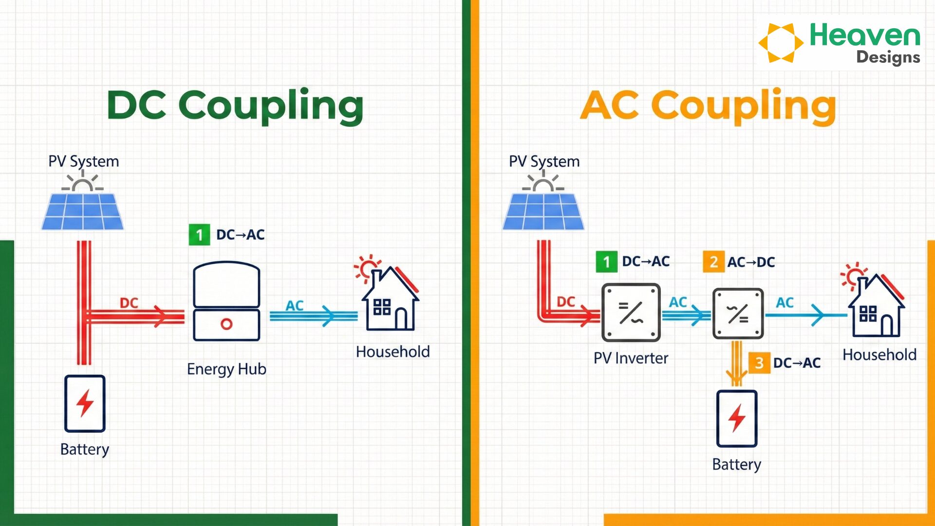
RTE (%) = (Energy out / Energy in) x 100Design implication: System-level RTE (at the AC terminals, including inverter and auxiliary losses) is typically 85–93% for LFP AC-coupled systems and 90–95% for LFP DC-coupled systems. The difference between cell-level RTE (97–99%) and system-level RTE (85–93%) represents the inverter conversion losses and auxiliary loads. Always specify RTE at the system level (AC terminals) for procurement contracts. See the BESS round-trip efficiency calculation guide for the full RTE Stack calculation methodology.
Term 8: Self-Discharge Rate
Definition: Self-discharge is the loss of stored energy over time when the battery is not in use. It is expressed as a percentage of capacity lost per month at a specified temperature and SoC.
Design implication: LFP self-discharge is typically 1–3% per month at 25 degrees C. This matters for off-grid systems with seasonal load patterns where the battery may sit at partial SoC for weeks between use cycles. A battery at 80% SoC losing 2% per month will reach 60% SoC after 10 months of non-use. For seasonal backup applications, specify the self-discharge rate and account for it in the autonomy calculation. NMC self-discharge is similar to LFP; lead-acid self-discharge is significantly higher (3–5% per month).
80%
Standard end-of-life SoH threshold (LFP C&I)
NREL Battery Cost Benchmark, 2024
3,000–5,000
LFP cycle life at 80% DoD (to 80% SoH)
IRENA Battery Storage Report, 2024
1–3%
LFP self-discharge rate per month (25 degrees C)
IEA Energy Storage Report, 2024
270 degrees C
LFP thermal runaway onset temperature
NREL Battery Safety, 2024
Term 9: Battery Management System (BMS)
Definition: The BMS is the electronic control system that monitors and protects the battery pack. It measures cell voltage, current, temperature, and SoC for each cell or cell group and enforces the safe operating limits (voltage, current, temperature cutoffs). The BMS communicates with the inverter-charger or energy management system (EMS) via CANbus, RS485, or Modbus to coordinate charge and discharge operations.
Design implication: The BMS specifications that matter most for design are: (1) SoC measurement accuracy (better than 3% for bankable projects), (2) cell voltage balancing method (active vs passive — active balancing is preferred for large BESS), (3) communication protocol compatibility with the project’s inverter and EMS, and (4) data logging capability (required for IE review and warranty claims). For DFI-financed projects, SCADA-compatible BMS with remote monitoring output is typically a funder requirement.
Term 10: Capacity Warranty
Definition: The capacity warranty is the manufacturer’s guarantee that the battery will retain a minimum percentage of its initial capacity (SoH) for a specified number of years or cycles, under defined operating conditions. A typical capacity warranty states: “Retain at least 80% of initial capacity after 3,000 cycles or 10 years at 80% DoD, 1C, 25 degrees C, whichever comes first.”
Design implication: Read the warranty conditions carefully — the “whichever comes first” clause means a battery that reaches 10 years before completing 3,000 cycles has its warranty expire at the calendar life milestone, even if the cells could continue cycling. For applications cycling more than 300 times per year, cycle count will likely be the binding warranty constraint. For applications cycling fewer than 300 times per year, calendar life may be the binding constraint.
Contract requirement: Specify that capacity warranty claims must be verified by an independent third-party test per IEC 62133 (for small systems) or IEC 62897 (for stationary energy storage above 0.5 kWh) rather than only by the manufacturer’s own BMS data. Manufacturer BMS data is not independently verifiable and has been disputed in several warranty claim proceedings.
Term 11: Temperature Operating Range
Definition: The temperature operating range specifies the minimum and maximum ambient temperature at which the battery can be charged and discharged without violating safety limits or voiding the warranty. It is different from the storage temperature range (the temperature range for non-operating storage).
| Parameter | LFP Typical | NMC Typical | Lead-Acid Typical |
|---|---|---|---|
| Discharge range | -20 to +60 degrees C | -20 to +55 degrees C | -20 to +50 degrees C |
| Charge range | 0 to +45 degrees C | 0 to +45 degrees C | -10 to +40 degrees C |
| Optimal performance range | +15 to +35 degrees C | +15 to +30 degrees C | +20 to +30 degrees C |
| Storage range | -40 to +60 degrees C | -20 to +60 degrees C | -40 to +50 degrees C |
Design implication: For projects in hot climates (ambient above 40 degrees C in summer), verify the battery’s charge temperature limit and the thermal management system required to keep the battery within the charge temperature range. LFP batteries that cannot be charged above 45 degrees C in a location with summer ambient temperatures of 45 degrees C require active cooling — an additional capital cost and auxiliary load that must be included in the project budget and energy model.
Term 12: Cell Chemistry (LFP vs NMC)
Definition: Battery cell chemistry defines the materials used in the cathode and anode of each cell, determining energy density, power density, cycle life, thermal stability, and cost. The two dominant chemistries for stationary solar storage are LFP (Lithium Iron Phosphate) and NMC (Nickel Manganese Cobalt Oxide).
Key differences for design:
| Parameter | LFP | NMC |
|---|---|---|
| Thermal runaway onset | ~270 degrees C (safer) | ~170–210 degrees C (requires more thermal management) |
| Energy density (Wh/kg) | 150–200 | 200–300 |
| Cycle life (80% DoD, to 80% SoH) | 3,000–5,000 | 1,500–2,500 |
| Round-trip efficiency (cell, DC-DC) | 97–98% | 98–99% |
| Cost ($/kWh installed, USA 2024) | $250–$350 | $230–$320 |
| Best applications | Daily cycling, hot climates, safety-critical | Space-constrained, cool climates, high energy density |
For solar storage applications in India, Africa, and most tropical regions, LFP is the default specification due to its superior cycle life, thermal safety, and calendar life at elevated ambient temperatures.
Term 13: Nominal Voltage and Energy Capacity
Definition: Nominal voltage is the average DC voltage of a fully charged cell or battery pack during discharge (not the peak voltage at 100% SoC). Nominal energy capacity is the energy stored in the battery at nominal voltage, expressed in kWh. Nameplate capacity refers to the manufacturer’s stated energy capacity under defined conditions (typically 25 degrees C, 0.2C discharge, 100% DoD).
Formula:
Nominal energy (kWh) = Nominal voltage (V) x Nominal capacity (Ah) / 1000For an LFP cell: 3.2V nominal x 100 Ah = 320 Wh = 0.32 kWh per cell.
Design implication: Always verify the basis for the stated capacity. A manufacturer stating “100 kWh capacity” may mean the nameplate at 100% DoD (not the usable energy within the BMS operating window) or may mean the usable capacity at 80% DoD. These two interpretations differ by 20%. For procurement contracts, specify the usable energy capacity within the BMS operating window (SoC_max - SoC_min), not the nameplate at 100% DoD.
Term 14: Power Rating (kW) and Energy Rating (kWh) — System Level
Definition: The power rating of a BESS system (in kW) is the maximum continuous charge or discharge power the system can deliver at the AC terminals. The energy rating (in kWh) is the usable energy that can be stored and retrieved within the BMS operating window. These are system-level specifications, including all power electronics losses.
Design implication: The power rating determines the BESS’s ability to respond to peak demand events (power is what shaves the peak; energy is what sustains the shave). A system with a high energy rating but insufficient power rating cannot respond to a sharp demand spike — it delivers the target power for too short a duration. Both ratings must be verified in the sizing calculation. See the BESS sizing walkthrough for the sizing methodology that coordinates power and energy.
Term 15: Thermal Management
Definition: Thermal management is the active or passive system that maintains the battery pack within its optimal operating temperature range. Active thermal management uses forced air (fans) or liquid cooling (pumped refrigerant or coolant) to remove heat from the cells during charge and discharge. Passive thermal management uses phase-change materials or natural convection — lower cost but less effective in high ambient temperature or high C-rate applications.
ACTIVE COOLING — USE WHEN
- Ambient temperature regularly exceeds 35 degrees C
- C-rate is above 0.5C continuous
- 10+ year warranty is required and ambient is above 30 degrees C
- System is sized for multiple cycles per day
- DFI or lender requires active thermal management documentation
PASSIVE ONLY — ACCEPTABLE WHEN
- Ambient temperature stays below 30 degrees C year-round
- C-rate is 0.5C or below
- Project life is 5–7 years with lower warranty requirements
- Budget is constrained and calendar life reduction is acceptable
- System is installed in a temperature-controlled indoor environment
Design implication: Active thermal management adds $10–$30/kWh to the BESS installed cost but extends calendar life by 2–5 years in hot climates. For a 500 kWh BESS in Gujarat, India (summer peak 45 degrees C), the active cooling cost of $5,000–$15,000 is typically recovered in extended calendar life and avoided early replacement costs within 3–5 years of the warranty period.
Download the BESS Parameter Dictionary worksheet
Heaven Designs' sample pack includes the BESS Parameter Dictionary as a fillable worksheet — enter your battery model's datasheet values and get a standardized comparison across all 15 parameters for procurement evaluation.
Get the sample pack →How BESS Vocabulary Differs Across Indian, US, and African Project Contexts
The 15 terms in the BESS Parameter Dictionary are universal — but how they appear in contracts, datasheets, and regulatory documents varies meaningfully across the three primary markets where Heaven Designs operates. Understanding these contextual differences prevents the most expensive vocabulary mismatches: those that are technically correct in one jurisdiction and contractually wrong in another.
India (MNRE, CERC, BIS context)
In India, BESS procurement for utility-scale projects operates under the Ministry of New and Renewable Energy’s 2023 Battery Storage Policy and the CERC Grid Storage Regulations. The vocabulary conventions that matter most in this context:
-
Usable energy is specified in kWh at the AC terminals (inverter output), not at the cell level. MNRE tender documents for BESS typically specify “AC-coupled usable energy” — meaning the round-trip efficiency stack (cell RTE + inverter conversion + auxiliary load) is already factored in. If a manufacturer’s datasheet gives cell-level energy and DC-DC RTE, the project team must calculate the AC-terminal usable energy independently.
-
C-rate in Indian tenders is often expressed as a “duration” (e.g., “4-hour storage system”) rather than a numeric C-rate. A 4-hour storage system is a 0.25C system (100% capacity discharged in 4 hours). Confirm the duration basis before comparing two tender specifications — some use rated capacity (nameplate), some use usable capacity (BMS window).
-
Cycle life warranty in CERC regulations follows the IEC 62897 testing standard. Procurement specifications should reference IEC 62897 explicitly to align the warranty language with the regulatory standard. Specifications referencing only “manufacturer’s internal testing” do not comply with CERC’s independent verification expectation for grid-connected BESS above 1 MW.
United States (NEC, UL 9540, IFC context)
In US project finance, BESS vocabulary is anchored to UL 9540 (Standard for Energy Storage Systems and Equipment) and the IFC (International Fire Code) battery storage provisions. The terms that matter most:
-
DoD is typically written into fire code compliance — UL 9540A testing uses the maximum DoD at which the battery will operate, and the fire code occupancy category depends partly on the chemistry and operating DoD. Specifying DoD in the procurement contract is not just an engineering decision; it is a fire code compliance input.
-
SoH tracking for US project finance is typically contractually required as a quarterly SCADA report to the lender’s independent engineer. The BMS data protocol and SCADA integration spec must support SoH export in a standardised format — typically CSV or Modbus — that the IE can parse without custom software.
Africa (DFI context — AfDB, IFC, USAID)
For DFI-financed projects in Africa, BESS vocabulary in procurement documents must align with the lender’s due diligence checklist. DFI engineering reviews for BESS typically request:
- C-rate and DoD specifications cross-referenced to the specific test standard (IEC 62133, IEC 62897, or IEEE 1679.1)
- Thermal management documentation aligned to the project’s ambient temperature profile (the Arrhenius calculation showing calendar life at actual operating temperature vs. 25 degrees C reference)
- BMS protocol specification confirming SCADA-compatible output for remote monitoring — a standard DFI covenant for projects with lender step-in rights
Tip. When preparing a BESS procurement specification for a project with international financing, specify both the term and the reference standard in every capacity and performance clause. "Usable energy per IEC 62897 AC-terminal measurement" is unambiguous across all jurisdictions. "Usable energy" alone is interpreted differently by every manufacturer's legal and contracts team.
How to Use BESS Vocabulary in Procurement Contracts and Term Sheets
The gap between knowing the 15 BESS terms and using them correctly in a procurement contract is where most project teams lose protection. The following clause-by-clause guide maps each vocabulary term to the specific contract section where it must appear — and the consequence of omitting or vaguely defining it.
Performance Guarantee Clause
The performance guarantee defines what the BESS must deliver over its contracted life. It must specify:
- Rated usable energy at AC terminals (kWh), measured per IEC 62897
- Rated continuous power at AC terminals (kW)
- Minimum round-trip efficiency at AC terminals (%) at 0.5C discharge, 25 degrees C
- Measurement boundary (AC terminals, not cell or DC bus)
Omitting the measurement boundary from the performance guarantee is the most common contract drafting error. A manufacturer that measures RTE at the DC bus (cell level) will report 97–99% RTE; the same system measured at the AC terminals delivers 85–93% system RTE. If the contract does not specify AC-terminal measurement, the manufacturer can satisfy the guarantee using cell-level data.
Warranty Clause
The warranty clause defines end-of-life conditions and manufacturer obligations. It must include:
- Minimum SoH at end of warranty term (typically 80%)
- Warranty term in both years and cumulative cycles (with “whichever occurs first” trigger)
- DoD at which cycle count is measured (typically 80%)
- C-rate at which cycle count is measured (typically 0.5C–1C)
- Ambient temperature at which cycle count is measured (typically 25 degrees C)
- Testing standard for capacity verification (IEC 62897 for systems above 0.5 kWh)
- Third-party verification requirement (independent test, not BMS data alone)
Liquidated Damages Clause
The LD clause translates vocabulary terms into financial consequences for underperformance. A well-structured LD clause links:
- Energy underperformance (actual usable kWh below warranted kWh) to a per-kWh LD rate
- RTE underperformance (actual RTE below warranted RTE) to an annual energy shortfall calculation
- SoH degradation faster than the warranty curve to an early warranty trigger provision
Without explicit vocabulary definitions in the LD clause, the manufacturer can dispute every underperformance calculation by asserting that the measurement methodology differs from the contract baseline.
Field tip. Request the manufacturer's proposed warranty clause language before the procurement contract is negotiated. Most tier-1 BESS manufacturers have standard warranty clauses written to their advantage — specifying the DoD and temperature that maximises their cycle life number and defining "capacity" as nameplate rather than usable. Counter-propose clause language that replaces their definitions with the IEC 62897 standard definitions. The vocabulary dictionary in this article provides the basis for that counter-proposal.
BESS Sizing Workflow: Applying the 15 Terms in a Design Calculation
Understanding BESS vocabulary in isolation is not enough — the terms must be applied correctly in a sizing calculation to determine the nameplate capacity required for a specific application. The following walkthrough shows how each vocabulary term feeds into a sizing calculation for a C&I demand charge reduction application.
Application parameters (example):
- Peak demand to shave: 300 kW for 90 minutes (1.5 hours)
- Required energy during peak: 300 kW × 1.5 hours = 450 kWh
- Desired project life: 10 years
- Operating profile: 250 cycles per year at 80% DoD
- Ambient temperature: 38 degrees C (Rajasthan C&I facility)
Step 1: Calculate usable energy required
The 450 kWh energy requirement is what the BESS must deliver at the AC terminals. This is the usable energy requirement.
Step 2: Account for round-trip efficiency
For an LFP AC-coupled system in this climate, assume system RTE of 87% (AC-in to AC-out). The energy input required to deliver 450 kWh:
Energy input = 450 / 0.87 = 517 kWhStep 3: Account for BMS operating window (DoD and SoC limits)
With 80% DoD (SoC between 95% and 15%):
Nameplate capacity at commissioning = 517 / 0.80 = 646 kWhStep 4: Account for end-of-life SoH degradation
At 250 cycles/year × 10 years = 2,500 cycles total. At 80% DoD in 38 degrees C ambient (temperature-derated cycle life), the SoH at 2,500 cycles is approximately 82%. The nameplate must be sized so the system still delivers 450 kWh usable at 82% SoH:
Nameplate required = 646 / 0.82 = 788 kWhRound to 800 kWh nameplate for procurement.
Step 5: Verify C-rate
Maximum discharge power = 300 kW. System C-rate = 300 / 800 = 0.375C. This is within LFP continuous rated range (0.5C typical rated; 0.375C < 0.5C). The C-rate is acceptable for the chemistry.
This five-step calculation uses six of the 15 BESS terms: usable energy, RTE, DoD, SoC, SoH, and C-rate — illustrating that the vocabulary terms are not academic definitions but active engineering parameters in every sizing calculation.
How to Read a Battery Datasheet: A Practical Checklist
A battery datasheet contains 8–15 specifications, of which 5–6 are decision-critical and the rest are secondary. Use this checklist when evaluating any battery product for a solar-plus-storage project.
- Nominal energy capacity (kWh): Is this at 100% DoD or at the BMS operating window? If not specified, ask the manufacturer for the usable capacity at their standard BMS limits.
- Cycle life: At what DoD and what end-of-life SoH threshold? If the datasheet says “3,000 cycles” without context, request the full specification: “[N] cycles at [DoD]% DoD to [SoH]% capacity retention at [C-rate]C, [temperature].”
- Round-trip efficiency: At the cell level (DC-DC) or at the system level (AC-AC)? At what C-rate and temperature? Cell-level RTE is always higher than system RTE — confirm which one is stated.
- Temperature operating range: What is the maximum charge temperature? Is active thermal management required to stay within the range at the project site’s summer ambient temperature?
- Calendar life: Is it specified? If not, assume 10 years at 25 degrees C as a conservative baseline and derate for actual operating temperature using the Arrhenius relationship.
- BMS communication protocol: CANbus, RS485, Modbus TCP? Confirm compatibility with the project’s inverter and EMS before specifying the battery.
According to IRENA’s 2024 Battery Storage for Renewables Market Status report, the absence of standardized datasheet formats for grid-connected batteries is one of the primary barriers to informed procurement decisions — with C-rate, cycle life DoD, and RTE measurement boundary being the most frequently misrepresented or ambiguously specified parameters in manufacturer datasheets.
How Heaven Designs Helps
Battery vocabulary expertise translates directly into better procurement specifications, more accurate energy models, and stronger warranty protection. Heaven Designs applies the BESS Parameter Dictionary to every storage project specification, ensuring the procurement contract language reflects the actual operating conditions and protects the project owner if the battery underperforms.
- Solar Rooftop Detailed Engineering Design — Complete engineering specification for rooftop solar-plus-BESS, including BESS procurement spec with all 15 parameters correctly defined for the application.
- Solar Ground Mount Design — Ground-mount solar-plus-storage design with utility-scale BESS specification, cycle life analysis, and thermal management requirements.
- MW-Scale Project Management Consultancy — Owner’s engineer services including BESS datasheet review, procurement specification writing, and acceptance test oversight for utility and large C&I projects.
- Download a sample deliverable — See the BESS Parameter Dictionary worksheet and a completed battery procurement specification from a real project.
Contact us to discuss BESS specification for your next solar-plus-storage project.
FAQ
What is C-rate in a battery and how do I calculate it?
C-rate is the ratio of discharge (or charge) power in kW to the energy capacity in kWh. Formula: C-rate = Power (kW) divided by Energy (kWh). A 500 kWh battery discharged at 250 kW operates at 0.5C and depletes in 2 hours. The same battery at 500 kW operates at 1C and depletes in 1 hour. C-rate must fall within the battery chemistry’s continuous rated range — 0.5C–1C for most LFP C&I applications — or the warranty is voided and cell degradation accelerates.
What is the difference between DoD and SoC?
SoC (State of Charge) is the current charge level expressed as a percentage of full capacity. DoD (Depth of Discharge) is the percentage of capacity that has been discharged from full. They are complementary: SoC (%) = 100% minus DoD (%). If a battery is at 20% SoC, it has been discharged to 80% DoD. DoD is used primarily for sizing and warranty specifications; SoC is used primarily by the BMS for real-time control. For a battery with BMS limits of 95% SoC maximum and 15% SoC minimum, the operational DoD is 95 minus 15 = 80%.
What does SoH mean for a BESS and why does it matter?
SoH (State of Health) is the battery’s current capacity expressed as a percentage of its original nominal capacity. SoH = 100% at delivery; SoH declines over time and with cycling. Most BESS warranties define end-of-life as the point SoH falls below 80%. SoH matters for project economics because a battery at 80% SoH can only deliver 80% of its initial energy output per cycle — directly reducing the revenue or demand charge savings the system generates. Monitoring SoH monthly allows early detection of abnormal degradation and supports warranty claims before the warranty expires.
How many cycles does an LFP battery deliver at 80% DoD?
LFP batteries typically deliver 3,000–5,000 cycles to 80% SoH at 80% DoD, 0.5C–1C discharge rate, and 25 degrees C operating temperature. At one full cycle per day (300 cycles per year for a demand charge reduction application cycling Monday through Friday), 3,000 cycles equals approximately 10 years of life — matching the standard 10-year LFP warranty. For applications cycling more frequently (twice daily), 3,000 cycles equals only 5 years. Always match cycle life to the application’s annual cycle count to verify the warranty covers the full project life.
What is a battery management system (BMS) and what does it control?
The BMS (Battery Management System) is the electronic control system that monitors and protects the battery pack. It measures cell voltage, current, and temperature in real-time and enforces operating limits — maximum charge voltage (preventing overcharge), minimum discharge voltage (preventing deep discharge), maximum charge and discharge current (preventing overcurrent), and maximum cell temperature (preventing thermal runaway). The BMS communicates with the inverter-charger or energy management system via communication protocols (CANbus, RS485, Modbus) to coordinate charge and discharge operations. For bankable projects, the BMS must provide data logging and remote monitoring output for IE review.
What capacity warranty language should I use in a BESS procurement contract?
Effective capacity warranty language specifies: the minimum SoH retention percentage (typically 80%), the warranty term (years and cycle count), the DoD at which the warranty applies (typically 80%), the C-rate and temperature of the test conditions, the measurement standard for capacity verification (IEC 62133 or IEC 62897), and the verification method (third-party test, not just BMS data). Example: “The BESS shall retain at least 80% of its initial rated usable capacity (kWh at the BMS operating window) after 3,000 charge-discharge cycles at 80% DoD, 0.5C rate, and 25 degrees C ambient, or 10 years from commissioning, whichever occurs first, verified by an independent third-party capacity test per IEC 62897.”
How does temperature affect LFP battery performance and life?
Temperature affects LFP batteries in two ways: operating performance and aging rate. At high ambient temperatures (above 35 degrees C), cell internal resistance decreases slightly (improving power delivery) but electrolyte side reactions increase — reducing cycle life and calendar life. LFP cycle life at 35 degrees C is typically 80–85% of the 25 degrees C specification; at 45 degrees C, it may be only 60–70%. At low temperatures (below 10 degrees C), cell internal resistance increases significantly — reducing both capacity and RTE. LFP batteries should not be charged below 0 degrees C (lithium plating risk). For projects in hot climates (India, Africa), active thermal management that keeps cells below 35 degrees C preserves warranty compliance and extends project life by 2–5 years relative to passive cooling.