A hybrid solar + diesel + battery system is the most technically demanding configuration in distributed energy, and the most consequential to get wrong. An undersized battery bank means the diesel generator runs continuously when it should be off. An oversized solar array with poor dispatch logic means solar energy is curtailed while diesel still burns. A system designed without real load profile data will underperform its design specification by 20–35% in the first year — and that underperformance compounds across a 15-year project life in ways that destroy project economics and DFI relationships. This guide covers the complete engineering process from load profiling through commissioning, using the 5-Step Hybrid System Design Protocol that Heaven Designs applies on projects from 15 kW rural clinics in West Africa to 5 MW industrial hybrid systems in India.
Direct answer. Hybrid solar + diesel + battery design follows five sequential steps: (1) load profiling — hourly kWh demand for 12 months with critical load separation, (2) solar array sizing — set the solar fraction target and size the PV array to meet it without excessive curtailment, (3) battery sizing — calculate energy buffer for nighttime supply and autonomy buffer for critical loads, (4) diesel dispatch strategy — determine when the generator runs, at what load, and in what priority sequence, (5) control logic specification — program the energy management system dispatch algorithm and protection coordination. HOMER Pro or equivalent simulation validates the entire system before procurement. The 5-Step Hybrid System Design Protocol structures each stage into bankable deliverables accepted by AfDB, IFC, USAID, and IREDA project finance teams.
This guide serves Tunde (African EPC pursuing DFI-financed off-grid and weak-grid projects) and Suresh (Indian developer designing hybrid systems for captive industrial and island-mode commercial applications). Currency references include $ (Africa/DFI context) and ₹ (India context) as appropriate. For the Africa telecom tower hybrid design case, see the related hybrid solar for African telecom towers analysis.
When Hybrid Beats Grid-Tied: The Decision Framework
Not every site needs a hybrid system. A grid-tied solar system without battery or diesel backup is simpler, cheaper, and appropriate for most sites with reliable grid access. Hybrid design adds cost and complexity that is only justified when specific conditions exist.
Hybrid solar outperforms grid-tied in four scenarios:
- Off-grid sites where there is no grid connection within economic reach (transmission infrastructure costs exceed $50,000–$100,000 per km in most of sub-Saharan Africa). The hybrid system is the only viable power solution.
- Weak-grid sites where grid power is available fewer than 8 hours per day, or where voltage and frequency fluctuations damage equipment. The hybrid system provides stable, conditioned power regardless of grid availability.
- High-diesel-cost sites where the existing backup generator runs more than 8 hours per day. At diesel prices above $0.40/L, adding solar and battery to displace diesel generation delivers payback periods of 3–6 years even at current BESS costs.
- Critical load sites where grid or generator failure causes economic or safety consequences (hospitals, cold chain storage, telecommunications, data centers). The hybrid system provides ride-through and backup duration beyond what a generator alone provides.
According to IRENA’s 2024 Renewables for Off-Grid Integration report, hybrid solar-diesel systems are now the lowest-cost electrification solution for sites with daily diesel consumption above 50 liters — covering the majority of off-grid telecom towers, health facilities, and small industrial loads in sub-Saharan Africa and island communities.
Definition. Solar fraction (SF) is the percentage of a site's total annual energy demand met by solar generation. A hybrid system designed to 75% SF means 75% of annual kWh comes from the PV array (directly or via battery), and 25% comes from the diesel generator. Increasing the solar fraction reduces diesel consumption but requires more PV capacity and battery storage, increasing capital cost. The optimal solar fraction is found by HOMER Pro simulation, not by rule of thumb.
Step 1 — Load Profiling: The Foundation That Everything Else Depends On
Load profiling is the single most important input in hybrid system design. Every sizing decision downstream — PV capacity, battery bank, generator size, dispatch logic — is a function of the demand profile. A system designed against an inaccurate load profile will be consistently wrong in ways that are expensive to fix after commissioning.
A complete load profile for hybrid system design consists of four data streams:
- Hourly average load (kW): 12 months × 24 hours = 288 data points minimum. Captures daily patterns (morning startup, midday peak, nighttime baseload) and seasonal variation (air conditioning load in summer, production schedule changes).
- Peak instantaneous demand (kW): The maximum simultaneous load the site ever draws. This is the critical parameter for generator and inverter sizing — not the average.
- Critical load subset (kW): The loads that must never lose power — medical equipment, process control, refrigeration, telecommunications. These determine the battery autonomy requirement.
- Deferrable load subset (kW): Loads that can shift in time — irrigation pumps, water heating, EV charging, laundry. These can be programmed to run when solar is abundant, reducing the battery size needed.
Common load profiling mistakes to avoid:
- Using the nameplate kW rating of all equipment (assumes 100% simultaneous operation — almost never true; coincidence factor is typically 0.65–0.80)
- Using average monthly kWh from utility bills (loses the hourly temporal structure needed for dispatch modeling)
- Ignoring seasonal variation (a telecom tower in the Sahel has very different summer/winter load profiles due to air conditioning)
- Missing motor starting kVA (5–7× nameplate kW for pump and compressor starts — critical for generator sizing)
The field tool for load profiling is a data logger installed at the main incomer for a minimum of 4 weeks — covering at least one weekend cycle and ideally one full production week. For new facilities without historical data, load profiling uses equipment lists with operating schedules and coincidence factors. For Africa projects, GOGLA’s Off-Grid Solar Market Trends Report 2024 provides load profile benchmarks for common site types (health clinics, schools, agro-processing, telecom) that can anchor the estimate when measured data is not available.
Field tip. For DFI-financed projects (AfDB, IFC), the load profile must be measured, not estimated. Install a data logger for 8 weeks minimum and submit the raw hourly data as an appendix to the HOMER Pro feasibility report. IFC reviewers will ask for the primary data — a load profile labeled "estimated from equipment list" fails technical due diligence.
Step 2 — Solar Array Sizing: Maximizing Solar Fraction Without Curtailment
Solar array sizing in a hybrid system is not the same as in a grid-tied system. In a grid-tied system, excess solar is exported to the grid. In a hybrid system, excess solar (beyond what the battery can absorb) is curtailed — it is wasted generation that still cost money to install. The solar fraction target must be set to maximize fuel savings without creating excessive curtailment.
The sizing process starts with the annual energy balance: the PV array must generate enough energy to meet the solar fraction target. If the site consumes 1,000 MWh/year and the target solar fraction is 75%, the array must generate 750 MWh/year of usable solar energy.
PV array sizing formula:
PV capacity (kWp) = (Annual usable solar energy target (kWh)) / (Annual specific yield (kWh/kWp))Specific yield depends on site irradiance (from Meteonorm or Solargis), module tilt, azimuth, temperature coefficient, and system losses. For a West Africa site with 2,000 kWh/m²/year horizontal irradiance, a well-designed fixed-tilt array typically achieves 1,600–1,850 kWh/kWp/year specific yield. For a South India site (Gujarat/Rajasthan), 1,700–1,950 kWh/kWp/year is typical.
However, the HOMER Pro simulation must verify that achieving the target solar fraction does not require curtailing more than 10–15% of solar generation. Excessive curtailment means the marginal solar kWh costs more to generate than it saves in diesel — at which point the optimal solar fraction has been exceeded.
| Solar Fraction | PV Capacity (100 kW load) | Battery Required | Daily Gen Hours | Curtailment |
|---|---|---|---|---|
| 50% | ~75 kWp | 100–150 kWh | 8–10 hr | <5% |
| 65% | ~110 kWp | 200–300 kWh | 5–7 hr | 5–8% |
| 75% | ~145 kWp | 350–500 kWh | 3–5 hr | 8–12% |
| 85% | ~195 kWp | 600–900 kWh | 2–3 hr | 12–20% |
The 75% solar fraction is the typical optimum for Africa hybrid systems at $0.35/L diesel cost and current LFP battery prices. At $0.50/L diesel or higher, the optimum shifts toward 80–85%.
Step 3 — Battery Sizing: Energy Buffer and Critical Load Autonomy
Battery sizing in a hybrid system solves two independent requirements: nighttime energy buffer and critical load autonomy.
Nighttime energy buffer: The battery must store enough daytime solar surplus to power the nighttime load (when the generator is off in the ideal dispatch scenario). For a site with 60 kW nighttime baseload and a target of 6 hours of nightly generator-off time, the energy buffer requirement is:
Buffer = 60 kW × 6 hr / DoD_max / RTE = 60 × 6 / 0.80 / 0.93 = 484 kWh nameplate (LFP)Critical load autonomy: The battery must sustain the critical load for the required autonomy period when neither solar nor generator is available. For a hospital with 30 kW critical load and 8-hour autonomy requirement:
Autonomy = 30 kW × 8 hr / DoD_max / RTE = 30 × 8 / 0.80 / 0.93 = 323 kWh nameplateThe battery bank must satisfy both constraints. The controlling constraint — whichever requires more kWh — determines the battery size. In most cases, the nighttime energy buffer is the larger requirement; the autonomy check verifies that critical loads are covered within the already-sized bank.
Definition. Depth of Discharge (DoD) is the percentage of the battery's nominal capacity that can be discharged before recharging. LFP lithium batteries support 80–90% DoD without significant life degradation. VRLA lead-acid batteries should be limited to 50% DoD. A higher DoD means a smaller (and less expensive) battery bank for the same usable energy — this is the primary reason LFP replaces lead-acid in hybrid systems despite the higher upfront cost per kWh nameplate.
For the BESS chemistry decision, LFP is preferred for hybrid systems in hot climates (sub-Saharan Africa, India) because of its thermal stability at temperatures above 35°C. NMC chemistry provides higher energy density but degrades more rapidly above 35°C ambient — a critical disadvantage for outdoor installations in tropical locations.
Step 4 — Diesel Generator Sizing and Dispatch Strategy
The diesel generator in a hybrid system must be sized to power the full site load without solar contribution — this is the worst-case scenario (multiple consecutive days of overcast weather that depletes the battery). Three parameters determine generator size:
- Peak site load (kW): The maximum simultaneous demand, as captured in the load profile.
- Motor starting kVA: Large motors draw 5–7× their nameplate kW during starting. The generator must supply this instantaneous reactive power. A 30 kW pump needs a generator capable of delivering 210 kVA (approximately 168 kW at 0.8 PF) for the 2–3 second start transient.
- Generator efficiency curve: Diesel generators operate most efficiently at 70–80% of nameplate load. Undersized generators run at 90–100% load (high fuel consumption, shortened engine life). Oversized generators run at 30–40% load (wet-stacking, increased maintenance). The optimal generator size is 120–130% of the peak continuous load it must handle.
60–85%
Optimal solar fraction (Africa hybrid)
IRENA Off-Grid Report, 2024
40–60%
Diesel savings vs. gen-only baseline
Heaven Designs HOMER models, 2025
4–6 yr
Payback period (Africa, $0.35/L diesel)
Heaven Designs project data, 2025
$0.25–$0.80
Diesel cost range per liter (Africa)
AfDB Energy Access Report, 2024
Dispatch strategies determine when the generator runs and in what sequence relative to solar and battery. Three standard strategies apply to hybrid systems:
| Dispatch Strategy | Best For | Solar Fraction Achieved | Generator Run Hours | System Complexity |
|---|---|---|---|---|
| Load-Following | High solar fraction sites, large battery bank | 70–85% | Low (2–4 hr/day) | Medium |
| Cycle Charging | High night-load, smaller battery | 55–70% | Moderate (4–6 hr/day) | Low |
| Combined Dispatch | Complex load profiles, DFI projects | 75–90% | Lowest (1–3 hr/day) | High |
In Load-Following dispatch, the inverter/charger runs solar and battery together to meet the load; the generator only starts when the battery reaches minimum state of charge (SoC). This maximizes solar fraction but requires a larger battery bank.
In Cycle Charging, when the generator runs, it runs at full nameplate capacity — charging the battery to full while powering the load simultaneously. The generator then shuts off until the next cycle. This suits high nighttime load sites where the generator is needed daily.
Combined Dispatch uses a sophisticated energy management system (EMS) that selects the mode based on real-time SoC, time-of-day, and solar irradiance forecast. It delivers the lowest LCOE but requires a capable EMS controller with programmable dispatch logic.
The 5-Step Hybrid System Design Protocol
The 5-Step Hybrid System Design Protocol is the proprietary engineering framework Heaven Designs uses to structure hybrid system design from raw load data to bankable deliverable package. It is applied consistently from 15 kW rural clinic projects to 5 MW industrial hybrid systems.
Load Profile Development
4–8-week data logger installation at site incomer. Hourly kW data exported, cleaned, and gap-filled. Peak demand, critical load, and deferrable load identified. Seasonal variation documented. Output: 12-month hourly load profile CSV for HOMER Pro, plus a load profile report with coincidence factors and critical load analysis.
HOMER Pro Sensitivity Simulation
Multi-year HOMER Pro simulation with site-specific Meteonorm or Solargis irradiance data. PV capacity, battery capacity, and generator size varied across a sensitivity matrix. LCOE surface plotted to identify the cost-optimal configuration. Solar fraction, fuel consumption, and unmet load verified against design targets. Output: HOMER simulation report with sensitivity tables and LCOE optimization plot.
Component Specification and Selection
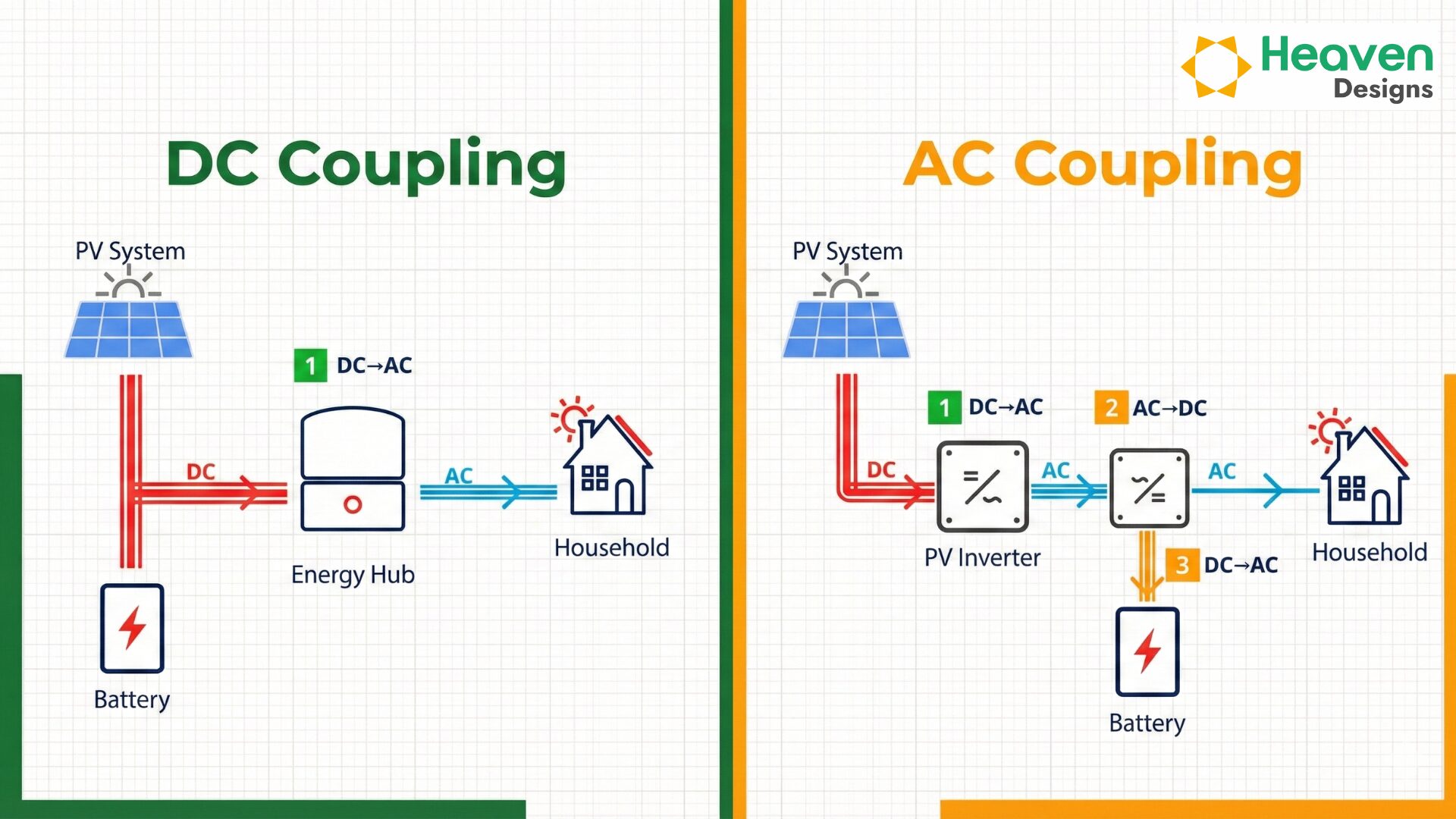
PV module, inverter-charger, battery bank, and generator specified against the HOMER-optimized sizing. For Africa projects: IFC/AfDB approved manufacturers, import tariff analysis, and in-country service partner confirmation. For India: ALMM-listed modules, BIS-compliant inverters, CEA Safety Regulations compliance. Inverter topology decision (AC-coupled vs DC-coupled) documented with rationale.
Electrical Design and Dispatch Logic Specification
Single-line diagram covering the full hybrid AC bus, DC protection scheme, battery management system (BMS) interfaces, and generator synchronization. Dispatch logic documented in a dispatch specification: SoC thresholds, generator start/stop setpoints, load priority sequence, and fault modes. Protection coordination study for generator paralleling with inverter output. Output: SLD, dispatch spec, protection coordination report.
Bankable Documentation Package
HOMER Pro simulation report, load profile data, equipment datasheets, performance guarantees, civil and structural drawings, electrical SLD and GA, protection coordination study, BOQ, commissioning procedure, and O&M plan — compiled into DFI submission format (AfDB, IFC, USAID, or IREDA as applicable). The package is reviewed by Heaven Designs' senior engineer before submission.
HOMER Pro Simulation Workflow
HOMER Pro by HOMER Energy is the industry-standard tool for hybrid system techno-economic simulation and is accepted by AfDB, IFC, USAID, and IREDA project finance teams as the basis for feasibility reports. The HOMER workflow for a hybrid project consists of six configuration steps:
- Load profile input: Upload the measured hourly load CSV or build from HOMER’s built-in load builder with monthly statistics and daily patterns.
- Solar resource input: Input the Meteonorm or Solargis monthly average irradiance (kWh/m²/day) with clearness index. For Africa, HOMER’s built-in NASA Surface Meteorology database can supplement where Solargis data is unavailable.
- Component library setup: Add the PV array, battery bank (with LFP chemistry parameters — capacity, round-trip efficiency, DoD limits, degradation rate), inverter-charger, and diesel generator with the site-specific fuel price and fuel delivery cost.
- Sensitivity inputs: Define the ranges for diesel price, battery cost, and solar capital cost that HOMER will vary in the sensitivity analysis. This quantifies the LCOE sensitivity to the most uncertain inputs.
- Dispatch strategy selection: Set the dispatch algorithm (Load-Following, Cycle Charging, or Combined) and the SoC setpoints for generator start and stop.
- Simulation and optimization: Run the HOMER optimization, which tests all feasible combinations of component sizes and ranks them by net present cost (NPC). Extract the cost-optimal configuration and verify it meets the solar fraction and unmet load constraints.
Watch out. HOMER Pro's default component costs are US market prices that are typically 20–40% higher than installed costs in India or Africa. Always override the component capital cost inputs with locally sourced quotes. A HOMER simulation run with default costs will show a project as uneconomic when it is actually viable — or show it as economic when the actual LCOE is higher than modeled.
Component Selection: Inverter-Charger, BMS, and Generator Controller
The three components that determine hybrid system performance — beyond the PV array, battery, and generator themselves — are the inverter-charger, the battery management system (BMS), and the generator controller.
Inverter-charger selection: The inverter-charger is the heart of a hybrid system. It manages power flow between the solar array (DC), battery (DC), generator (AC), and loads (AC). Multimode inverter-chargers (Victron Quattro, SMA Sunny Island, Schneider Conext) operate in grid-tied, off-grid, and hybrid modes and execute the dispatch logic automatically based on SoC thresholds and load measurements. Key specifications: AC input capacity (kVA) must exceed the generator output; AC output capacity (kVA) must exceed the peak site load; battery charge current (A) must not exceed the battery bank’s maximum charge rate (C-rate × capacity).
BMS (Battery Management System): The BMS protects the battery bank from overcharge, overdischarge, and thermal events. It monitors cell voltage, current, temperature, and state of health (SoH) for each cell or cell group and communicates with the inverter-charger via CANbus or RS485. For LFP batteries in hybrid systems, the BMS must support the cell balancing algorithm (active or passive) appropriate for the cell chemistry and pack configuration. Do not source battery banks without an integrated BMS — this is non-negotiable for bankable projects.
Generator controller: For hybrid systems where the generator parallels with the inverter output on the AC bus (common in Combined Dispatch systems), the generator controller must execute synchronization, load sharing, and anti-islanding protection. Diesel generators with electronic governors and AMF (Automatic Mains Failure) controllers are compatible with most hybrid inverter-chargers. Confirm the generator controller communication protocol (Modbus, CANbus, or dry-contact) matches the EMS interface.
Download a sample hybrid system engineering package
Heaven Designs' sample pack includes a HOMER Pro simulation report, single-line diagram, and BOQ for a 150 kW hybrid solar + diesel + battery system designed for DFI submission. See the 5-Step protocol in practice.
Get the sample pack →Africa vs India Hybrid Design: Key Differences
Hybrid system designs in Africa and India differ in three important dimensions: irradiance quality and seasonality, fuel cost (which drives the economic case for solar fraction), and the regulatory and financing documentation framework.
| Design Parameter | Africa (Sub-Saharan) | India (Weak-Grid Industrial) |
|---|---|---|
| Irradiance data source | Meteonorm Africa / Solargis | NSRDB India / Solargis India |
| Diesel cost | $0.25–$0.80/L (varies by location) | ₹85–₹110/L |
| Optimal solar fraction | 65–85% (high diesel cost) | 50–70% (grid backup available) |
| Battery chemistry preferred | LFP (heat tolerance, cycle life) | LFP (increasingly) or VRLA (lower cost) |
| Generator paralleling standard | IEC 60034, ISO 8528 | IS 12834, CEA Safety Regulations |
| Documentation standard | IFC Performance Standards, AfDB E&S Policy | CEA Connectivity Regs, IS 16221, CEIG |
| DFI accepted yield tool | HOMER Pro, PVsyst (for PV component) | PVsyst 7.4+ (IREDA/PFC requirement) |
For Africa-specific mini-grid feasibility methodology, the solar mini-grid feasibility in sub-Saharan Africa article covers the additional demand characterization and community engagement steps required for rural electrification projects. According to the African Development Bank’s Desert to Power Progress Report 2024, the AfDB has committed $20 billion to African renewable energy access through 2030, with hybrid solar-diesel-battery systems as the primary technology for off-grid and mini-grid deployment.
Commissioning Checklist for Hybrid Systems
Commissioning a hybrid system is more complex than commissioning a standard grid-tied system because multiple power sources must be verified to operate correctly in isolation and in combination.
Pre-energization checks:
- Battery bank: Verify SoC at 50–60% before first charge, confirm BMS communication active, verify protection fuses and DC isolation switches
- Inverter-charger: Verify firmware version, dispatch logic parameters programmed per design specification, generator start/stop SoC setpoints confirmed
- Generator: Verify governor settings, AMF controller configuration, fuel level, oil level, coolant level, exhaust clearance
Commissioning sequence:
- Energize battery bank in isolation — verify BMS cell voltages, temperature readings, and communication with inverter
- Energize inverter in off-grid mode — verify AC output voltage and frequency (within ±2% of nominal)
- Connect loads gradually — verify load sharing, voltage stability at full load
- Start generator in isolation — verify synchronization parameters before connecting to AC bus
- Connect generator to AC bus — verify load sharing, power factor, and protection relay response
- Energize PV array — verify MPPT operation, battery charging response, and curtailment behavior at full SoC
How Heaven Designs Helps
Hybrid system design requires a specific engineering stack: HOMER Pro proficiency, load profiling expertise, dispatch logic specification, protection coordination, and DFI documentation fluency. Heaven Designs maintains this capability across both India and Africa market projects, with engineers who have completed hybrid system designs from 15 kW rural clinic scale to 5 MW industrial hybrid.
- Solar Ground Mount Design — Full civil and electrical design for the solar array component of a hybrid system, including terrain analysis and structural engineering for the mounting system.
- Solar Rooftop Detailed Engineering Design — For rooftop-mounted hybrid PV arrays, complete IFC-grade structural assessment, mounting design, and SLD.
- MW-Scale Project Management Consultancy — Owner’s engineer support through hybrid system design, procurement, and commissioning for projects above 1 MW, including DFI reporting.
- Solar Civil and Structural Engineering — Foundation design, structural calculations, and civil works drawings for hybrid system installations.
- Download a sample deliverable — See a HOMER Pro report, SLD, and BOQ from a real hybrid project before you commission your own.
Contact us to start the 5-Step Hybrid System Design Protocol for your next project.
FAQ
What is the correct sequence for hybrid solar + diesel + battery design?
The correct design sequence is: (1) measure the load profile — hourly kWh for 12 months with critical load identification, (2) run HOMER Pro sensitivity simulation to find the cost-optimal PV/battery/generator configuration, (3) specify components against the HOMER output with locally sourced pricing, (4) design the electrical system including dispatch logic and protection coordination, (5) assemble the bankable documentation package for DFI or lender review. Skipping or compressing any stage creates a system that underperforms its specification.
How is the solar fraction determined for a hybrid system?
The solar fraction is determined by HOMER Pro sensitivity analysis — not by a fixed rule of thumb. The optimal solar fraction is the point on the LCOE optimization surface where adding more solar capacity costs more per kWh than it saves in diesel. Typical optimal solar fractions are 60–85% depending on diesel price, battery cost, and load profile. Higher diesel costs (common in remote Africa locations above $0.50/L) push the optimal solar fraction toward 80–85%.
What battery chemistry is recommended for hybrid systems in hot climates?
Lithium Iron Phosphate (LFP) chemistry is preferred for hybrid systems in hot climates (sub-Saharan Africa, India) because LFP has significantly better thermal stability than other lithium chemistries. LFP cells maintain acceptable cycle life up to 45°C ambient with proper thermal management, compared to NMC cells which degrade more rapidly above 35°C. VRLA lead-acid has lower upfront cost but requires active temperature management above 35°C and only 50% usable DoD versus 80% for LFP — increasing the nameplate battery size needed for the same autonomy.
What documentation does a hybrid system need for AfDB or IFC financing?
AfDB and IFC project finance for hybrid systems typically requires: a HOMER Pro simulation report with multi-year sensitivity analysis and measured load profile data; an IFC Performance Standard compliance review (environmental and social); equipment datasheets and manufacturer qualifications meeting IFC approved vendor criteria; a protection coordination study for the generator-inverter interface; a commissioning and acceptance test procedure; an O&M plan with training documentation; and civil and structural drawings for mounting systems. Heaven Designs produces all components of this package in AfDB/IFC submission format.
How large should the diesel generator be in a hybrid solar + battery system?
The diesel generator in a hybrid system should be sized at 120–130% of the maximum load the system will ask it to cover — which, in a well-designed hybrid, is the peak load minus any simultaneous solar and battery output. This is typically 60–80% of the standalone generator size for a site replacing a diesel-only system. The generator must also handle motor starting kVA for large equipment (5–7× nameplate kW). A generator sized too small trips on overload; a generator sized too large runs below 40% load causing wet-stacking and premature engine wear.
What is the difference between off-grid and weak-grid hybrid system design?
Off-grid hybrid systems have no grid connection — the diesel generator is the only backup source and the system must meet 100% of the site’s energy needs. Weak-grid hybrid systems connect to an unreliable grid providing intermittent power (6–12 hours per day or less). Weak-grid systems are designed with the grid as an additional source alongside solar, battery, and diesel — with dispatch logic prioritizing solar first, then battery, then grid when available, then diesel as last resort. Weak-grid design is more complex because the grid connection adds an additional power source with its own availability profile that the HOMER simulation must model explicitly.
How do I know if a hybrid system is more cost-effective than grid extension?
Compare the levelized cost of electricity (LCOE) from the hybrid system against the cost of grid extension (transmission infrastructure investment amortized over the connection life) plus the grid tariff. For sites more than 5–10 km from the nearest grid connection point, hybrid systems are typically cheaper in Africa. In India, the threshold is closer to 15–25 km from a 33 kV substation. HOMER Pro calculates the hybrid LCOE directly; the grid extension cost must be estimated from infrastructure cost benchmarks or utility quotes.