A solar mounting structure is not a commodity. The wrong choice — a galvanized steel system in a coastal environment, an aluminum system on a 30-degree slope in a 55 m/s wind zone, a ballasted system on a waterproofed membrane that cannot take point loads — turns into a field problem that costs more to fix than the original structure. Yet mounting structure selection is often treated as a procurement afterthought, with the EPC specifying “aluminum racking” without considering the foundation, the wind load, the roof deck capacity, or the 25-year corrosion environment.
Direct answer. Choosing a solar mounting structure requires evaluating five parameters: material (aluminum alloy vs. galvanized/hot-dip-galvanized steel vs. stainless for marine), foundation type (roof-penetrating L-foot, ballasted, driven pile, helical pier, concrete ballast block), panel geometry (tilt angle, row spacing for GCR), wind and snow load requirements (ASCE 7-22 for US, IS 875 Part 3 for India), and the building or ground capacity to accept the resulting loads. A 5 MW utility ground-mount and a 50 kW commercial rooftop require fundamentally different decisions on all five parameters.
This guide serves all ICPs: Rohan evaluating racking for a 2 MW rooftop in Pune, Mike specifying a residential tilt mount in Phoenix, Jennifer comparing ground-mount options for a 500 kW C&I system in Texas, Suresh reviewing a 50 MW ground-mount BOQ for a SECI-tendered project, and Tunde comparing options for a 3 MW hybrid system in Nigeria where steel sourcing is local.
Material Selection — Aluminum vs Steel vs Hybrid
The material decision drives corrosion resistance, structural strength, fabrication complexity, and cost. No single material wins across all applications.
~60%
US commercial rooftop projects use aluminum racking
SEIA US Solar Market Insight, 2025
~80%
Indian utility ground-mount projects use galvanized steel
Bridge to India Solar Market Report, 2025
25 yr
Minimum design life for utility PV mount structures
IEC 62548 / IS 875 guidance
85 μm
Min galvanizing thickness for Indian utility projects (IS 2629)
BIS IS 2629, heavy-duty corrosion category
| Material | Corrosion Resistance | Structural Strength | Weight | Best Applications |
|---|---|---|---|---|
| 6061-T6 Aluminum | Excellent — no galvanic risk with anodizing | Lower yield strength than steel | Light — 2.7 g/cm³ | US/EU rooftop, coastal environments |
| Galvanized steel (HDG) | Good — dependent on coating thickness | High yield strength | Heavy — 7.8 g/cm³ | Indian/African ground-mount, inland |
| Pre-galvanized steel | Moderate — less durable than HDG at cut edges | High yield strength | Heavy | Light-duty carport, residential |
| Hot-dip galvanized + epoxy | Very good for aggressive environments | High | Heavy | Coastal, high-humidity, industrial |
| Stainless 316 | Excellent — marine environments | Moderate | Medium | Offshore, floating, marine C1M |
| Hybrid (aluminum rails, steel main posts) | Application-dependent | Balanced | Medium | Large commercial rooftop |
Watch out. Galvanic corrosion between aluminum rails and galvanized steel clips is a 25-year performance risk in humid environments. When mixing aluminum and galvanized steel at connection points, specify EPDM isolation tape or non-conductive isolation washers at every contact point. This is not an optional detail — galvanic corrosion at mounting clips is responsible for a significant share of structural failures in coastal rooftop systems after 8–12 years.
Foundation Type — The Decision That Determines Everything Else
The foundation choice is more consequential than the material choice. It determines civil cost, ground disturbance, reversibility, and structural load path.
Rooftop Foundations
| Foundation Type | Roof Type Required | Penetration | Load Distribution | Best For |
|---|---|---|---|---|
| L-foot with lag bolt | Composition shingle, metal, concrete tile | Yes — through roof deck | Point loads at rafters | US residential, light commercial |
| T-bar standing seam clamp | Standing seam metal | No penetration | Clamped to seam | Metal roofs, zero-penetration requirement |
| Adhesive / bonded mount | TPO, EPDM, PVC membrane | No penetration | Distributed bond area | Flat membrane commercial |
| Ballasted (concrete block) | EPDM, TPO, PVC membrane | No penetration | Distributed dead load | Flat commercial, high wind secondary ballast |
| Adjustable pedestal | TPO, EPDM, concrete, pavers | No penetration | Distributed over paver area | Flat with pavers, accessible rooftop |
The selection among rooftop foundation types depends on the membrane or deck type. Using a penetrating L-foot on a TPO membrane without a proper flasher kit voids the membrane warranty — a risk that can cost more than the entire racking system to remediate. Using a ballasted system on a flat roof whose dead load capacity is already near its design limit is a structural failure waiting to happen.
Definition. A ballasted racking system uses concrete blocks or ballast pads to provide the restoring force against wind uplift without penetrating the roof membrane. The blocks are sized using wind uplift calculations (ASCE 7-22 for US, IS 875 for India) to ensure the system stays in place under design wind loads. The critical check is whether the roof deck can carry the additional dead load — a fully ballasted 500 kW system can add 8–15 psf distributed dead load to the roof.
Ground-Mount Foundations
For ground-mount projects, the foundation decision is driven by soil type, site topography, seismic zone, and the project’s reversibility requirements.
| Foundation Type | Best Soil | Installation Method | Reversibility | Cost Relative |
|---|---|---|---|---|
| Driven pile (steel H-pile or tubular) | Dense sand, firm clay, gravel | Impact or vibratory hammer | Removable — pull posts | Low — fastest installation |
| Helical pier (screw pile) | Variable — engineered per pull-out test | Hydraulic torque head | Removable | Medium |
| Concrete ballast block | Any — no penetration | Pour in place or precast | Removable | Medium |
| Drilled pier (augered with concrete) | Rocky, very soft, or expansive soils | Drill rig + concrete pour | Not removable | High |
| Spread footing | Rocky, hard soil | Excavate + pour | Not removable | High |
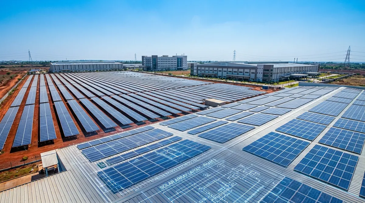
Driven steel piles are the dominant foundation type for utility-scale ground-mount in India and the US because they are the fastest and lowest-cost installation method for the soil types common in solar parks (agricultural plains, semi-arid flatlands). For our solar ground mount design service, we specify pile type and penetration depth based on site soil report and the pull-out capacity required by the wind uplift calculation.
Geometry — Tilt Angle, Row Spacing, and GCR
The mounting geometry determines energy yield, structural loads, and land use. These are linked — optimizing one at the expense of others produces a project that wins on one metric and loses money on another.
| Geometry Parameter | Effect on Yield | Effect on Wind Load | Effect on Land Use |
|---|---|---|---|
| Higher tilt angle (>20°) | Higher winter yield at high latitudes | Significantly higher wind uplift and drag | Requires larger row spacing for same GCR |
| Lower tilt angle (<10°) | Lower winter yield | Much lower wind load | Allows tighter row spacing / higher GCR |
| East-west layout (facing east and west) | Lower peak, flatter daily profile | Lower wind load than south-facing at same height | Higher GCR — 20–30% more panels per acre |
| Fixed south-facing | Optimized peak yield | Moderate wind load | Standard GCR 35–45% for most climates |
| Single-axis tracker | 15–25% yield gain over fixed | Complex — varies by stow position | GCR typically 30–40% |
| Dual-axis tracker | 35–40% yield gain | Highest — structure must carry load in all orientations | Lowest GCR — most land per MW |
For our ground-mount layout work, ground coverage ratio (GCR) optimization runs alongside the structural load calculation because these interact: a GCR of 0.45 with 15° tilt on a 2 MW site produces a fundamentally different structural spec than a GCR of 0.30 with 20° tilt on the same site.
Field tip. East-west mounting on flat commercial rooftops often delivers more energy per square meter of usable roof area than south-facing tilt, because the higher GCR offsets the slightly lower per-panel yield. For rooftops where dead load capacity is the constraint, east-west also reduces wind load — allowing smaller ballast blocks or fewer penetration points. Run the east-west vs. south-facing comparison before finalizing the rooftop layout; the answer is not always obvious from first principles.
The 5-Dimension Mounting Selection Framework
This is Heaven Designs’ Mount-Fit Matrix — the five-dimension evaluation we run for every project before specifying a mounting structure, ensuring that material, foundation, geometry, load, and economics align.
Environment Classification
Classify the corrosion environment: C1 (dry inland), C2 (moderate), C3 (coastal < 5 km), C4 (industrial/coastal), C5/CX (marine/offshore). Match material and coating specification to the corrosion category. This is the decision that governs 25-year structural integrity — getting it right is not optional.
Structural Load Envelope
Calculate wind uplift and downforce, snow load (for relevant climates), and dead load (module weight + structure weight). For US projects, use ASCE 7-22. For Indian projects, use IS 875 Part 3. The load envelope defines the minimum structural capacity required — structure selection must match or exceed this before any other consideration.
Foundation Compatibility Check
For rooftop: confirm roof membrane type, deck type, and dead load capacity. For ground-mount: confirm soil report results and required pull-out capacity. The foundation selection follows from these constraints — not from cost alone. A driven pile that cannot meet pull-out requirements is worthless regardless of its material cost advantage.
Geometry Optimization
Run the GCR and tilt angle optimization using energy yield modeling (PVsyst or equivalent). Confirm that the chosen geometry does not increase wind loads beyond the structural envelope established in Step 2. For trackers, confirm the stow position load is within the foundation's capacity — tracker loads in stow during high-wind events often govern the structural design.
Economics and Sourcing Feasibility
Evaluate material cost (₹/kg for India, $/lb for US), fabrication lead time, local sourcing availability, and the DCR (Domestic Content Requirement) applicability for Indian government tenders. A technically superior structure that cannot be sourced within the project's procurement window is not a viable choice — sourcing risk is a structural decision input, not an afterthought.
Comparing Fixed-Tilt vs Tracker Mounting for Ground-Mount Projects
For ground-mount solar projects above approximately 500 kW, the fixed-tilt vs. single-axis tracker decision is a significant engineering and economic choice.
| Factor | Fixed-Tilt Ground-Mount | Single-Axis Tracker |
|---|---|---|
| Yield gain over fixed | Baseline | +15 to +25% in low-latitude, high-DNI sites |
| Foundation complexity | Standard pile + concrete spreader | Requires torsional resistance — stronger piles |
| Wind load | Relatively predictable | Complex — stow position load governs |
| Civil area requirement | Standard | 10–20% more land for same capacity at same GCR |
| O&M complexity | Very low | Requires actuator maintenance, software |
| Cost premium (EPC) | Baseline | ₹12–18 lakhs/MW additional (India 2025) |
| Best application | Rooftop, high-latitude, constrained land | Utility ground-mount, low latitude, open terrain |
For Suresh’s utility-scale India projects competing in SECI auctions: the tracker vs. fixed-tilt decision often comes down to the tariff bid math. According to Mercom India’s 2025 tracker market report, tracker adoption in utility-scale India projects reached 55% of new MW commissioned in FY2024-25 — a significant shift from 30% just three years prior, driven by falling tracker costs and the yield advantage in low-latitude Rajasthan and Gujarat sites.
Need a mounting structure specification package?
Download a sample structural engineering deliverable — includes material spec, foundation type justification, load summary, and STAAD Pro calculation excerpt.
Get the sample pack →How Heaven Designs Supports Mounting Structure Engineering
Heaven Designs’ civil and structural engineering team has specified, modeled, and delivered mounting structure calculations for rooftop, ground-mount, carport, and floating solar projects across India, the US, Africa, and the Middle East. Our solar civil and structural engineering service covers the full Mount-Fit Matrix for every project.
- Solar Civil and Structural Engineering — Material selection, foundation engineering, load analysis per ASCE 7-22 (US) or IS 875 Part 3 (India), STAAD Pro structural models, and PE-stamped calculation packages.
- STAAD Pro Report and Calculations — Structural analysis reports for mounting structures for lender or AHJ submission, for projects where the racking manufacturer’s ICC-ESR is insufficient.
- Solar Ground Mount Design — Ground-mount layout, GCR optimization, foundation type recommendation, and full civil + structural deliverables.
- Solar Rooftop Detailed Engineering Design — Rooftop mount specification including membrane compatibility, dead load check, and penetration or ballast design.
- Download a sample deliverable — See an actual structural package before you engage.
For mounting structure questions that are too project-specific for a generic answer, contact our structural team — we provide free initial scope reviews.
Corrosion Environment Classification for Indian Solar Sites
The corrosion environment at the project site is frequently underestimated in mounting structure specifications. India’s diverse climate zones range from arid inland environments (C2 corrosion class) to highly corrosive marine coastal environments (C5 corrosion class) that require fundamentally different material treatments.
According to NREL’s 2023 review of PV system balance of systems costs, corrosion-related mounting structure failures are one of the top three O&M cost drivers for solar projects in high-humidity and coastal environments. The cost of replacing corroded mounting structures mid-project life (Year 10–15) typically exceeds ₹8–15 lakh/MW — entirely avoidable with correct material specification at design stage.
Classification guide for Indian solar sites:
| Environment Class | Description | Indian Examples | Required HDG (IS 4759) |
|---|---|---|---|
| C2 — Low | Standard rural/inland outdoor | Rajasthan inland, MP plateau | 55 μm minimum |
| C3 — Medium | Industrial atmosphere, coastal > 10 km | Gujarat industrial, TN inland | 85 μm minimum |
| C4 — High | Chemical industry, coastal 2–10 km | Coastal Karnataka, AP coast | 85 μm + protective topcoat |
| C5 — Very high | Marine, within 1–2 km of sea | Goa coast, Chennai port area | 120 μm + stainless fasteners |
For floating solar applications on freshwater reservoirs, see the future of floating solar in India for specific material requirements for submerged and partially submerged components.
The IRENA renewable power cost report notes that balance of system cost reduction — including mounting structure optimisation — is one of the two primary levers for continued solar LCOE reduction in developing markets.
Structural Standards — IS 800 for India, AISC for the USA
The structural design of solar mounting structures must comply with the applicable national structural code:
India — IS 800:2007 (General Construction in Steel)
IS 800:2007 is the primary code for steel structure design in India. Solar mounting structures must be designed per IS 800:2007 using Limit State Design (LSD) methodology. Combined with IS 875 Part 3 for wind load determination, this creates the complete structural analysis framework for Indian ground-mount and rooftop solar. According to the Bureau of Indian Standards civil engineering division, IS 800:2007 is the current mandatory reference for steel structure design in India, including solar mounting applications.
USA — AISC 360 and ASCE 7-22
American Institute of Steel Construction (AISC) AISC 360 governs steel structure design in the US. Combined with ASCE 7-22 wind load calculations (see the ASCE 7-22 wind load guide for detail), AISC 360 provides the design basis for US ground-mount and rooftop solar structures. The IBC (International Building Code) references both ASCE 7 and AISC 360 as the mandatory structural standards.
The connection between structural code compliance and project bankability: lenders and independent engineers require that structural designs for solar projects be certified by a licensed structural engineer confirming compliance with the applicable code. A mounting structure specification without a structural engineer’s certification is not accepted in IREDA or PFC project finance — or in US AHJ permit submissions above 100 kW.
FAQ
What is the most common mounting structure material for Indian utility-scale projects?
Hot-dip galvanized (HDG) structural steel is the dominant material for Indian utility-scale ground-mount projects. It offers high structural capacity, wide local sourcing availability, and acceptable corrosion resistance for the inland and semi-arid sites typical of large Indian solar parks. The BIS standard IS 2629 specifies minimum galvanizing thickness — 85 microns for C3 environments. For coastal sites in Gujarat, Tamil Nadu, or Andhra Pradesh, additional coating systems or stainless hardware at critical joints are recommended.
Can I use a ballasted racking system on any flat roof?
No. Ballasted systems require the roof deck to carry significant additional dead load — typically 5–15 psf in addition to the existing dead and live loads. Before specifying a ballasted system, obtain the structural engineer of record’s confirmation that the existing roof structure can carry this load. For older buildings (pre-2000 construction), the original design often had no provision for rooftop mechanical or solar loads, and the structural upgrade cost can exceed the cost of the solar system itself.
How do trackers affect foundation requirements compared to fixed-tilt?
Single-axis trackers transmit a fundamentally different load pattern to their foundations compared to fixed-tilt structures. Fixed-tilt structures transmit primarily vertical loads (module weight + wind vertical component) with moderate horizontal wind drag. Trackers must also resist torsional loads — the torque tube twists under wind loads when the panel is angled, and this torque is transmitted directly to the pile. Tracker foundation piles must therefore be designed for torsional stiffness, not just vertical and horizontal capacity. Many pile failures on early tracker installations resulted from using fixed-tilt pile specifications without accounting for torsional loading.
What is the minimum galvanizing thickness required for solar mounting structures in India?
IS 2629 and SECI tender specifications typically require a minimum hot-dip galvanizing thickness of 70–85 microns for solar mounting structures, depending on the corrosion category of the site. Coastal sites (within 10 km of the sea) require the higher end of this range plus may require additional protective coatings. Confirm the galvanizing specification in the tender technical specification before fabrication — under-specification is a factory inspection rejection that delays project commissioning.
How do I calculate the required ballast weight for a flat rooftop system?
Ballast weight calculation follows the ASCE 7-22 wind uplift analysis. The calculated net uplift pressure (in psf) on the panel array is applied to the panel area and divided by the number of ballast blocks to determine the required weight per block. The calculation must also include a safety factor and confirm that the ballast block itself does not become a projectile under extreme wind — ballast block edge distances from the roof perimeter are typically restricted by the racking manufacturer’s engineering data. Heaven Designs runs this calculation for every ballasted rooftop system as part of the structural package.
What is the typical pile penetration depth for a driven steel pile in a solar ground-mount?
Typical penetration depths for driven steel H-piles or round tubular piles in solar ground-mount projects range from 1.5 to 3.5 meters, depending on soil type, pile size, and required pull-out capacity. Sandy or loose soils require deeper penetration to develop sufficient friction and end bearing. Clay soils develop capacity through friction and may require shorter but larger-diameter piles. The penetration depth is determined by the geotechnical engineer based on the soil report and the calculated uplift load from the structural analysis — it cannot be assumed from typical values without a site-specific analysis.