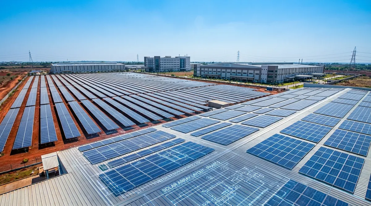
STAAD Pro is the structural analysis software that most Indian solar EPC companies’ structural engineers are either using or being asked to use by their clients’ independent engineers. For utility-scale ground-mount projects in India, a STAAD Pro model of the mounting structure has become a near-universal requirement for lender due diligence and government tender submissions. Yet most solar engineers who come to STAAD Pro from a civil engineering background find the software’s workflow unfamiliar when applied to the repetitive, lightweight, wind-dominated structures that characterize solar mounting — structures that behave very differently from the building frames STAAD Pro was originally designed for.
Direct answer. STAAD Pro structural modeling for solar ground-mount structures involves six steps: geometry setup (input column, purlin, and rafter nodes and members), section property assignment (steel hollow sections or hot-rolled), material property assignment (IS 2062 or ASTM A36 equivalent), load case definition (dead, wind per IS 875 Part 3, seismic per IS 1893 if required), load combination definition per IS 800 or AISC 360, and analysis run followed by result extraction (member utilization ratios, deflection, and foundation reactions). The output feeds into the structural calculation report that lenders and AHJs require.
This guide is for all ICPs working with structural engineering — Rohan whose Indian EPC clients are increasingly requiring STAAD Pro reports for DISCOM submissions, Mike whose commercial US rooftop clients need PE-stamped structural calculations, and Suresh whose utility-scale India projects go through IREDA or PFC lender review where the IE checks structural calculations directly. Heaven Designs produces STAAD Pro reports as a standalone service — this guide explains what goes into them so EPC engineers understand what they are receiving and why each element matters.
Why STAAD Pro for Solar — and Not Manual Calculations
For small rooftop systems (< 100 kW), manual structural calculations using standard beam formulas and manufacturer’s ICC-ESR data are typically sufficient. For larger systems, the reasons to use STAAD Pro (or equivalent FEA software like SAP2000) become compelling.
500 kW+
System size where STAAD Pro analysis is typically required in India
Heaven Designs project data, 2025
3–5 days
Typical time to produce a STAAD model + report for a standard ground-mount
Heaven Designs internal benchmark
IS 800
Indian steel structure design standard STAAD uses by default
Bureau of Indian Standards, IS 800:2007
Manual calculations become inadequate when:
- The structure is statically indeterminate — multiple load paths, not simple beams.
- The wind load varies across the structure (zone-based wind coefficients per IS 875 Part 3 or ASCE 7-22).
- The foundation reactions at each pile need to be calculated precisely for pile sizing.
- The IE or lender requires a structural calculation model, not just beam-formula outputs.
- The structure uses non-standard sections (custom-fabricated hollow sections) not covered by handbook tables.
Definition. STAAD Pro (Structural Analysis and Design Professional) is a finite element analysis and design software package developed by Bentley Systems. For solar structures, it is used in its 3D frame analysis mode — the structure is modeled as a series of nodes (joint locations) and members (beams or columns between nodes), with loads applied at nodes or distributed along members. The software solves for member forces, stresses, and deflections, then checks member capacity against IS 800, AISC 360, or other design codes.
Step 1 — Geometry Setup: Nodes, Members, and Structure Type
The first step in a STAAD Pro solar model is defining the geometry. For a standard fixed-tilt ground-mount structure, the key components are:
- Ground posts (columns): Vertical or raked members from the foundation to the top and bottom chord connection points.
- Top and bottom chord (purlins or rafters): Horizontal or inclined members connecting posts at the top (at the inclined panel support plane) and bottom (at the lower panel edge).
- Cross-bracing: Diagonal members providing lateral stability in the longitudinal direction (along the row axis).
- Module support rails: Longitudinal members that the module mounting clips attach to — these carry the panel weight and wind load from the module into the structure.
Node input convention for a single row structure:
A typical 2-post structure for 4 modules wide looks like this (coordinates in meters):
Node 1: (0, 0, 0) — bottom of post 1
Node 2: (0, 1.2, 0) — bottom chord connection, post 1
Node 3: (0, 2.4, 0) — top chord connection, post 1
Node 4: (4.0, 0, 0) — bottom of post 2
Node 5: (4.0, 1.0, 0) — bottom chord connection, post 2
Node 6: (4.0, 2.2, 0) — top chord connection, post 2
The height difference between Node 3 and Node 6 (2.4 - 2.2 = 0.2 m over 4.0 m horizontal = 5% slope, approximately 3° tilt) represents the panel mounting angle. For a 10° tilt, the height difference increases proportionally.
Watch out. STAAD Pro operates in a right-hand coordinate system by default: X is horizontal (along the row), Y is vertical, and Z is out of the plane (perpendicular to the row, i.e., north-south for a typical east-west oriented row). Many first-time solar modelers confuse the Z and Y directions when setting up inclined structures, resulting in loads being applied in the wrong direction. Always verify the model orientation by running a simple gravity load check before applying wind loads.
Step 2 — Section Properties: What Steel Sections to Use
Solar mounting structures in India typically use square hollow sections (SHS), rectangular hollow sections (RHS), or angles for the secondary members. The section table in STAAD Pro includes IS standard sections — open it via the User Table feature and load the Indian Steel section database.
| Member Type | Common Indian Section | STAAD Pro Table Name |
|---|---|---|
| Ground post (main column) | SHS 100×100×6 or RHS 100×60×4 | ISH / SHS Indian |
| Top/bottom chord | RHS 100×50×4 | ISH |
| Purlin / rail | Lip channel (lipped C) 75×45×2.5 | Custom user table |
| Cross-brace | Angle 50×50×5 or flat 30×5 | ISA Indian |
| Module clamp rail | Custom aluminum section | User-defined section |
For US projects using ASTM A500 Grade B or C HSS (hollow structural sections), STAAD Pro has the AISC steel database. The section names follow AISC convention: HSS4×4×3/16, HSS6×4×1/4, etc.
Defining a custom section in STAAD Pro:
If the rail section is a custom extrusion (common for manufacturer-proprietary aluminum rails), use the DEFINE USER TABLE command to input the section properties: area (A), moment of inertia (Ix, Iy), section modulus (Sx, Sy), and torsional constant (J). These values come from the racking manufacturer’s technical data sheet.
Step 3 — Material Properties: IS 2062 and ASTM A36 / A500
STAAD Pro’s material database includes IS 2062 (Indian structural steel) by default. For solar mounting structures:
- Columns and main members: IS 2062 E250 (Fe 410) — yield strength 250 MPa, ultimate 410 MPa
- Light secondary members: IS 2062 E350 (Fe 490) if higher strength is needed to reduce section size
- Hot-dip galvanized sections: Same material properties as base metal — galvanizing adds corrosion resistance, not structural capacity
For US projects: ASTM A36 (yield 250 MPa, ultimate 400 MPa) for standard structural shapes, ASTM A500 Grade C (yield 317 MPa) for HSS.
Field tip. When modeling hot-dip galvanized sections in STAAD Pro, use the nominal (un-galvanized) section properties. Galvanizing adds approximately 0.3–0.5 mm to each surface — which is negligible for section properties but must be accounted for when checking section-to-section fit at connections. Do not add a thickness correction to the STAAD section properties for galvanizing.
Step 4 — Load Cases: Dead, Wind, and Seismic
This is the most critical and most frequently incorrect step in solar STAAD models. The load cases must reflect the actual loads on the structure, applied in the correct direction and at the correct locations.
Dead Load (DL)
Dead load on a solar structure includes:
- Self-weight of steel structure: STAAD Pro calculates this automatically with the SELFWEIGHT command — use it to avoid manual calculation.
- Module weight: Distributed across the module support rails. A 600 W module weighs approximately 28–32 kg (62–70 lbs). Applied as a UDL on the top chord members: UDL = (module weight × modules per row) / (top chord length).
- Purlin weight (if not in model): If the module support rails are not modeled explicitly, add their weight as an additional UDL.
Wind Load per IS 875 Part 3
Wind load on solar structures is the dominant load case for member sizing in most Indian solar installations. IS 875 Part 3 (2015) provides the framework, but solar panels are not a standard structure type covered in IS 875. Engineers use the pressure coefficients for “pitched roofs” and “flat roofs” as approximations, adjusted for the panel’s inclination.
The applied wind pressure on the panel surface:
p = 0.6 × Vz² × Cp (in N/m²)
Where:
- Vz = design wind speed at panel height (m/s), calculated from basic wind speed Vb with terrain and topography factors
- Cp = net pressure coefficient = Cpe (external) - Cpi (internal, for enclosed structures) or external pressure coefficient only for open structures
For a solar mounting structure (open structure, not enclosed), the wind pressure acts directly on the panel surface:
- Uplift (suction, leading face): Cp ≈ -1.2 to -1.8 (varies by panel tilt and wind direction angle)
- Downward (pressure, leading face): Cp ≈ +0.5 to +0.9
These values should be verified against the racking manufacturer’s wind tunnel test data if available — many racking manufacturers have conducted certified wind tunnel tests that provide more accurate Cp values for their specific geometries. The NREL report on wind loads for solar panels provides validated pressure coefficients for ground-mount configurations that can supplement IS 875 Part 3 approximations.
Load Combinations per IS 800
The governing load combinations for IS 800 limit state design:
- 1.5 DL (factored dead load — governs foundation settlement check)
- 1.5 DL + 1.5 WL (uplift wind with dead load acting to resist uplift — use 0.9 DL when dead load is beneficial)
- 0.9 DL + 1.5 WL (critical for uplift: dead load reduced by 0.9 when unfavorable)
- 1.2 DL + 1.2 WL + 1.2 LL (combined, if live load applicable)
- 1.5 DL + 1.5 EL (seismic — check if IS 1893 applies)
STAAD PRO ADVANTAGES FOR SOLAR
- Handles all load combinations automatically
- Provides foundation reactions per post — direct pile sizing input
- IS 800 code check built-in for member utilization ratio
- Repeatable model for multiple row configurations
- Output directly usable in structural calculation report
COMMON BEGINNER MISTAKES
- Applying wind load as nodal force instead of surface pressure
- Forgetting the 0.9 DL + 1.5 WL combination for uplift
- Using Vz at ground level instead of at panel centroid height
- Not including self-weight of rails and purlins
- Running analysis before verifying coordinate system orientation
Step 5 — Running the Analysis and Reading Results
The STAAD Pro ANALYZE LOAD LIST command runs the stiffness analysis for all load combinations. After analysis, the key results to extract for a solar structure report are:
Member Utilization Ratio (MUR)
The MUR is the ratio of the actual member force to the member’s capacity under IS 800. A MUR < 1.0 means the member passes. A MUR > 1.0 means the member fails and must be upsized or a stronger section specified. For solar structures, the governing check is typically axial + bending interaction (combined loading) in the column members.
STAAD Pro reports MUR values through the SELECT OPTIMUM command or through the post-processing CODE CHECK function. The output table lists each member, the governing load combination, the actual force, the capacity, and the utilization ratio.
Foundation Reactions
Foundation reactions (vertical load, horizontal shear, moment) at each support node are extracted through the PRINT SUPPORT REACTIONS command. These feed directly into the pile design — the geotechnical engineer uses the maximum vertical uplift (upward reaction) and compression (downward reaction) to size the pile.
Deflection Check
The maximum deflection of the module support rail under dead load should not exceed L/300 (where L is the rail span between purlins) to prevent module frame cracking at the mounting clips. STAAD Pro reports deflections via the PRINT JOINT DISPLACEMENTS command for each load case.
The 6-Step Solar STAAD Pro Workflow
This is Heaven Designs’ Solar Frame Analysis Sequence (SFAS) — the six-step process our structural engineers follow for every STAAD Pro solar model to produce a reliable, lender-ready calculation.
Structural Geometry Input
Define nodes and members for a single representative row. Model one bay length (one purlin span) and extract forces — then extrapolate to the full row if the geometry is repetitive. For non-repetitive rows (corner rows, rows near obstructions), model those separately.
Preliminary Section Assignment
Assign the racking manufacturer's specified sections to each member type. Run a first pass. If MURs are all well below 1.0, consider downsizing to reduce steel cost. If any MUR > 1.0, upsize that member and re-run. The goal is MUR 0.75–0.90 for main members — enough margin for uncertainty without over-engineering.
Load Application and Combination
Apply all load cases (DL, WL in all directions, SL if applicable). Define IS 800 load combinations. Verify the self-weight command is active. Run a visual check of the deformed shape under each load case — an unexpected deformation pattern usually indicates a geometry or support condition error.
IS 800 Code Check
Run the IS 800 code check via the post-processing module. Extract the MUR for every member. Identify the governing load combination and governing limit state (tension, compression, bending, or combined) for each critical member. Document in the calculation report.
Foundation Reaction Extraction
Extract maximum uplift and compression reactions at each support node for the governing load combinations. Present in a table: support node, load combination, vertical reaction (uplift/compression), horizontal shear (N-S, E-W). These values are the geotechnical engineer's input for pile design.
Report Compilation
Compile the STAAD report into a structured engineering calculation document: design basis, site parameters, load calculations, model description, code check results, foundation reactions, and section approval table. This is the document the IE or lender reviews — clarity and completeness matter as much as the numbers.
Want to see a STAAD Pro solar structure calculation report?
Download a sample STAAD Pro report for a 2 MW ground-mount structure — includes model geometry, load calculations per IS 875 Part 3, IS 800 code check results, and foundation reactions.
Get the sample pack →How Heaven Designs Delivers STAAD Pro Solar Calculations
Heaven Designs’ STAAD Pro report and calculations service is purpose-built for the solar ground-mount structural analysis that EPCs and developers need for lender due diligence, DISCOM submissions, and contractor tendering. Our structural team has built STAAD Pro models for projects from 100 kW to 100 MW across India, the Middle East, and Africa.
- STAAD Pro Report and Calculations — Complete structural analysis model, IS 800 code check, foundation reactions, and formal calculation report in 3–5 business days for standard ground-mount structures.
- Solar Civil and Structural Engineering — Full civil + structural package including STAAD Pro analysis, foundation design, and stamped drawing set for AHJ or lender submission.
- Solar Ground Mount Design — Layout, GCR optimization, structural spec, and STAAD Pro analysis bundled into a single engineering deliverable.
- Download a sample deliverable — See a sample STAAD Pro report before engaging.
For urgent project requirements — lender review approaching, IE requesting calculation package — contact our structural team to discuss turnaround on a standard ground-mount analysis.
FAQ
Which STAAD Pro version should I use for solar structure analysis?
STAAD Pro CONNECT Edition (the current Bentley subscription version) is the most widely used in 2026 and supports IS 800:2007, IS 875:2015, and AISC 360-22. Earlier perpetual license versions (STAAD Pro V8i) work for the analysis itself but may not have the latest code updates for IS 800:2007 limit state design — confirm the version’s IS 800 implementation before using it for lender-facing calculations.
Can I model a single-axis tracker in STAAD Pro?
Yes, but tracker modeling is significantly more complex than fixed-tilt modeling. The tracker’s torque tube introduces torsional loads that must be explicitly modeled — the rotating assembly creates a torsional moment at the pile connections that can govern the pile design. Most tracker manufacturers provide structural calculation templates that their engineers use with STAAD Pro — request these from the tracker supplier before starting the model. Modeling trackers from scratch without the manufacturer’s templates is time-consuming and prone to errors in the torsional load path. For a detailed treatment of tracker-specific foundation and load considerations, see the solar tracker foundation design guide.
What is the difference between IS 800:1984 (WSD) and IS 800:2007 (LSM) in STAAD Pro?
IS 800:1984 used Working Stress Design (WSD), where loads are applied at their nominal (unfactored) values and member stresses are compared to allowable stresses (a fraction of yield). IS 800:2007 uses Limit State Method (LSM), where loads are factored (1.5DL, etc.) and member capacities are factored (resistance factors). STAAD Pro’s IS 800 code check can run either version — confirm which version your project requires. As of 2026, most Indian utilities and lenders require IS 800:2007 (LSM). Using IS 800:1984 for a new project that requires 2007 will trigger an IE comment.
How do I verify that my STAAD Pro model is correct before submitting it?
Standard verification checks for a solar STAAD Pro model: (1) Gravity load check — apply 1.0 DL and verify that the vertical support reactions sum equals the total applied dead load. (2) Deformed shape check — under uplift wind load, the model should deflect upward uniformly — any downward deflection of panel-supporting members under uplift load indicates a load direction error. (3) Hand calculation spot-check — for one critical member, manually calculate the expected axial force under a simple load case and compare to STAAD Pro output. A 5% or less difference is acceptable; larger differences indicate a geometry or load input error.
Does STAAD Pro handle the IS 875 Part 3 terrain factor automatically?
STAAD Pro does not automatically calculate terrain factor (k2) from the wind zone map — you must input the design wind speed Vz at the relevant height after calculating it manually or with a spreadsheet tool per IS 875 Part 3. The software then applies the wind pressure from the input Vz. Some consulting engineers use a separate IS 875 calculation workbook to generate Vz at multiple heights, then input the results into STAAD Pro as height-varying wind loads. For solar structures where the panel height above grade is 0.5–4 m, the height variation in wind speed is small — a single Vz at the panel centroid height is typically sufficient.